background image

CAUTION: 

 Always be sure that the tool is switched OFF and unplugged before installing or 

removing the drill bit. 

 The  SDS-plus  drill  bit  will  be 

off-center when rotating with no-load, 

but  it  will  align  with  the  center 

automatically  during  operation  and 

its precision won

’t be affected. 

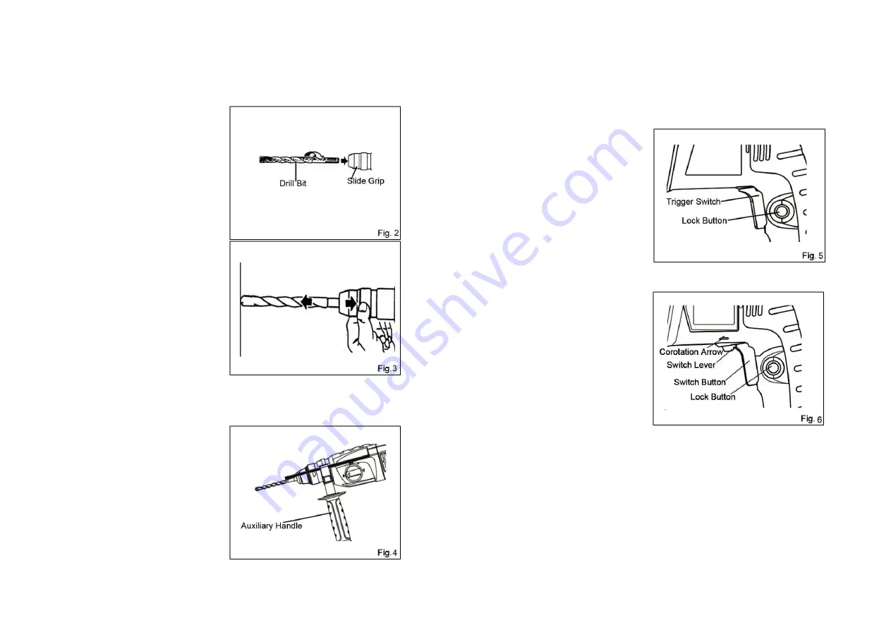
Clean the bit shank and smear it with 

bit grease before installation. 

To install the drill bit (SDS-plus shank), 

fully pull back the slide grip and insert 

the  drill  bit  as  far  as  it  will  go  while 

rotating. (

Fig. 2

By releasing the slide grip, the drill bit 

will be secured automatically. 

To  remove  the  SDS-plus  drill  bit,  fully 

pull  back  and  hold  the  slide  grip  and 

the drill bit can be removed. (

Fig. 3


Auxiliary Handle 

Always  use  the  auxiliary  handle 

ensure  operating  safety.  Loosen  the 

auxiliary 

handle 

by 

turning 

it 

counterclockwise,  swing  it  to  the 

desired position and then tighten it by 

turning clockwise. (

Fig. 4

Switch Action 

CAUTION: 

 Before plugging in the tool, always check to see that the trigger switch actuates 

properly and returns to the 

“OFF” position when released. 

To  start  the  tool,  simply  pull  the  switch 

trigger.  Release  the  switch  trigger  to 

stop.   

For continuous operation, pull the switch 

trigger  and  then  push  in  the  lock  lever. 

To stop the tool from the locked position, 

pull  the  switch  trigger  fully,  and  then 

release it. The rotating speed of the tool 

becomes  faster  and  faster  until  it 

reaches  the  full  speed  during  the 

process of pressing the switch. (

Fig. 5

The  switch  of  Z1C-FF05-26  is  with 

positive  and  negative  going  motion, 

which  can be  used  to  change  the  tool

’s 

direction  of  rotation.  You  can  only 

change it when the tool completely stops 

rotating,  otherwise  the  tool  will  be 

damaged.  (

Fig.  6

)

  Set  the  direction of 

rotation for hammer drilling, drilling and chiseling always to right rotation.


Depth Gauge 

CAUTION: 

 The  depth  gauge  cannot  be  used  at  the  position  where  he  depth  gauge  strikes 

against the tool body. 


-7-                                                                            -8-


Summary of Contents for DZC05-26

Page 1: ...Edition 3 Jan 2017 Read through carefully and understand these instructions before use ...

Page 2: ...r use reduces the risk of electric shock 9 If operating a power in a damp location is unavoidable use a residual current device RCD protected supply Use of an RCD reduces the risk of electric shock NOTE The term residual current device RCD may be replaced by the term ground fault circuit interrupter GFCI or earth leakage circuit breaker ELCB Personal Safety 10 Stay alert watch what you are doing a...

Page 3: ...placement parts This will ensure that the safety of the power tool is maintained VOLTAGE WARNING Before connecting the machine to a power source receptacle outlet etc be sure the voltage supplied is the same as that specified on the nameplate of the machine A power source with voltage greater than that specified for the machine can result in SERIOUS INJURY to the user as well as damage to the mach...

Page 4: ...ing the operating mode or the gears inside the tool maybe damaged If the drill bit gets stuck by the steel hidden in the wall during impact drilling and the tool rotates due to the kickback hold the handle and auxiliary handle firmly to avoid personal injuries The Operating mode can be changed by turning the operating mode selector Drilling Operation When impact drilling on the concrete or stone t...

Page 5: ...n tighten it by turning clockwise Fig 4 Switch Action CAUTION Before plugging in the tool always check to see that the trigger switch actuates properly and returns to the OFF position when released To start the tool simply pull the switch trigger Release the switch trigger to stop For continuous operation pull the switch trigger and then push in the lock lever To stop the tool from the locked posi...

Page 6: ...o so could result in serious hazard 3 Maintenance of the Motor The motor unit winding is the very heart of the power tool Exercise due care to ensure the winding does not become damaged and or wet with oil or water 4 Inspecting and Replacing Carbon Brushes Remove and check the carbon brushes regularly Replace when they wear down to the limit mark Keep the carbon brushes clean and free to slip in t...

Page 7: ...Z1C FF05 26 Z1C FF05 26B 11 12 ...

Page 8: ...Sleeve 37 Damping Washer 11 O Ring 38 O Ring 12 Seal Ring 39 Adaptor Sleeve 13 Thrust Ring 40 Roundwire Snap Ring for Hole 14 Impact Bolt 41 Striker 15 Label 42 O Ring 16 Gear Housing 43 Piston 17 Seal Ring 44 Washer 18 Needle Bearing 45 Piston Pin 19 Needle Bearing Cover 46 Shaft Sleeve 20 Clamping Ring 47 Seal Ring 21 Operating Mode Selector 48 Metal Sheet for Support 22 O Ring 49 Gear Housing C...

Page 9: ...sing 80 Carbon Brush Holder 81 Carbon Brush EXPLANATION OF GENERAL VIEW Z1C FF05 26B 1 Dust Cap 28 Clutch Spring 2 Roundwire Snap Ring for Shaft 29 Roundwire Snap Ring for Shaft 3 Washer 30 Clutch Gear 4 Roundwire Snap Ring 31 Lock Pin 5 Locking Sleeve 32 Cylinder 6 Clamping Ring 33 Pin 7 Steel Ball 34 Clutch Plate 8 Clip Board 35 Retaining Ring for Hole 9 Compression Spring 36 Guide Sleeve 10 Ret...

Page 10: ...79 Motor Housing 80 Carbon Brush Holder 81 Carbon Brush EXPLANATION OF GENERAL VIEW Z1C FF05 26C 1 Dust Cap 28 Clutch Spring 2 Roundwire Snap Ring for Shaft 29 Roundwire Snap Ring for Shaft 3 Washer 30 Clutch Gear 4 Roundwire Snap Ring 31 Lock Pin 5 Locking Sleeve 32 Cylinder 6 Clamping Ring 33 Pin 7 Steel Ball 34 Clutch Plate 8 Clip Board 35 Retaining Ring for Hole 9 Compression Spring 36 Guide S...

Page 11: ...ge 64 Deep Groove Ball Bearing 91 Steel Band 65 Bearing Retainer 92 Trapezoid Square neck Bolt 66 Cross Recessed Countersunk Head Screw 93 Lock Screw 67 Washer 94 Steel Band Base 68 Armature Assembly 95 Hex Nut 69 Insulation Washer 96 Clip Board 70 Ball Bearing 97 Auxiliary Handle 71 Rubber Sleeve 98 Nut 72 Baffle Plate 73 Pan Head Tapping Screw 74 Stator Assembly 75 Inductance 76 Nameplate 77 Mot...

Reviews: