Electric and Instrument
EL-20
Structure
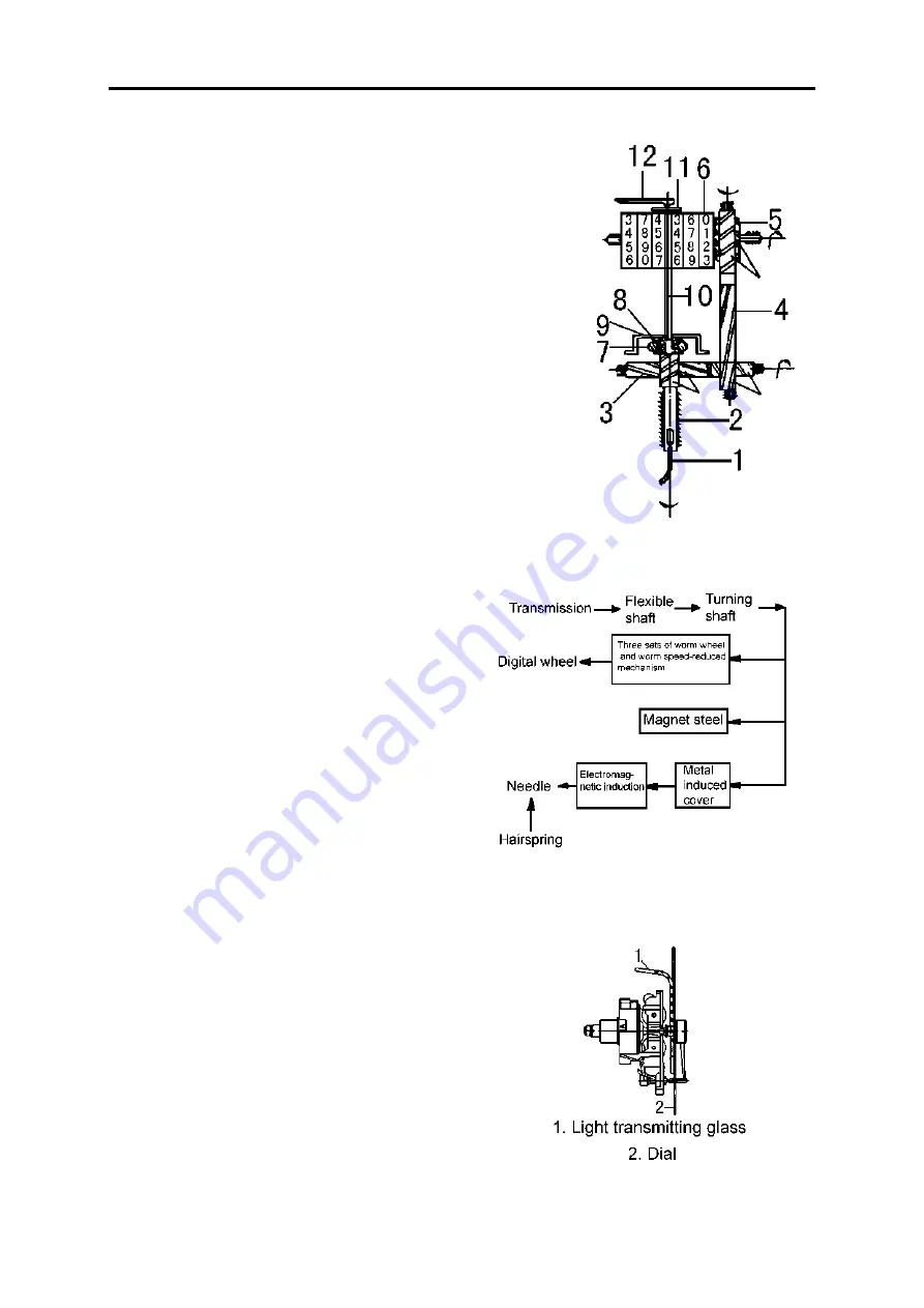
The speedometer is used to indicate the vehicle driving speed and
the accumulated driving distance. It comprises a speed and a mileage
unit which records vehicle driving mileage. These two units are inte-
grated into one body and driven by the flexible shaft which is connected
with transmission output shaft.
The mileage unit records the driven mileage of the vehicle in order
to do necessary maintenance on mileage. The counter is divided into an
accumulated counter and a day counter. The speed unit indicates the
transient speed of the vehicle. It is convenient to control the vehicle
speed so as to obtain safety, economy and high efficiency.
1.Flexible shaft 2.Drive shaft 3.Worm and lateral shaft
4.Worm and vertical shaft 5.Worm wheel 6.Digital wheel
7.Magnetic ring 8.Temperature compensated ring
9.Inductive aluminum cover 10.Needle shaft
11.Hairspring 12.Needle
Working principle
Drive of speedometer
The flexible shaft (driven by transmission main
shaft) mounted on the back of the transmission is driven
by pulling the square connector into the square hole at
the outside of the speedometer turning shaft which drives
the digital wheel through three sets of worm wheel and
worm.
Indication of odometer
When the flexible shaft drives the speedometer turn-
ing shaft to rotate, the magnetic steel on the drive shaft
rotates simultaneously, causing the eddy current within
the inductive cover, which also produce magnetic field.
Both fields interact on each other to produce deflecting
torque. The higher the vehicle speed is, the larger the
deflecting torque is, which can be indicated by the needle
deflection. When the needle deflecting torque of the hair-
spring, the needle will stay at the appropriate speed
value. The needle deflecting angle is proportional to the
speed of the speedometer turning shaft, that is, the vehi-
cle speed, causing the needle to indicate various speed.
Summary of Contents for DFA1101GZ5AD6J-907
Page 1: ...DFA1101GZ5AD6J 907 SERVICE MANUAL DONGFENG AUTOMOBILE CO LTD 2006 05 ...
Page 24: ...Clutch CL 8 ...
Page 34: ...Transmission MT 9 16 Lift the countershaft out by using crane or hoist Transmission mainshaft ...
Page 63: ...Transmission MT 38 ...
Page 123: ...Brake System BR 12 ...
Page 131: ...Cab BF 7 Cab External Trims ...
Page 133: ...Cab BF 9 Front and rear window Cab door seal strip ...
Page 134: ...Cab BF 10 Door outside molding Foot step shield and mat ...
Page 149: ...Air conditioner and Heater BF 25 Schematic Circuit of Air condition System ...
Page 150: ...Air conditioner and Heater BF 26 ...
Page 165: ...Electric and Instrument EL 14 Electric wiring diagram ...


