Electric and Instrument
EL-23
Instrument assembly and disassembly
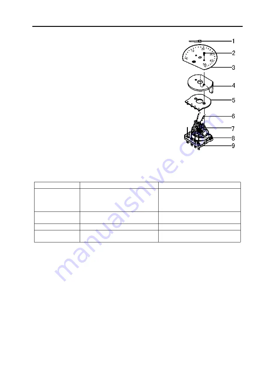
Before disassembling the instrument, pull out needle 1, and then
loosen two screws 2.
When disassembling the printed-circuit board; pull it out directly
after welding off two wires 9(the printed board and blade connector are
directly connected together through a spring blade socket on the board).
Generally, do not disassemble the unit core. If it has to be disassem-
bled, weld off both the upper and the lower hairsprings, and the conduc-
tive blade at first so as not to damage the hairsprings In addition, do not
break the coil output wire.
1.Needle 2.Screw 3.Dial 4.Light guiding glass
5.Printed circuit-board 6.Connection wire 7.Bracket
8.Blade connector 9.Base
Trouble analysis
Trouble
Case
Repair
The instrument doesn't
work
Circuit broke
Sensor damaged
Instrument burnt out
Check wire connection and connector with
socket's contact
Replace sensor
Replace instrument
Needle shakes abnor-
mally
Wire connection is not good
Integrated body damaged
Check wire connection
Replace integrated body
Needle clicked
There's foreign objects in the core
Remove foreign objects
Needle doesn't return
to zero
Needle slacked
Core is clicked by foreign objects
Press the needle firmly and turn to zero
Remove foreign objects
Summary of Contents for DFA1101GZ5AD6J-907
Page 1: ...DFA1101GZ5AD6J 907 SERVICE MANUAL DONGFENG AUTOMOBILE CO LTD 2006 05 ...
Page 24: ...Clutch CL 8 ...
Page 34: ...Transmission MT 9 16 Lift the countershaft out by using crane or hoist Transmission mainshaft ...
Page 63: ...Transmission MT 38 ...
Page 123: ...Brake System BR 12 ...
Page 131: ...Cab BF 7 Cab External Trims ...
Page 133: ...Cab BF 9 Front and rear window Cab door seal strip ...
Page 134: ...Cab BF 10 Door outside molding Foot step shield and mat ...
Page 149: ...Air conditioner and Heater BF 25 Schematic Circuit of Air condition System ...
Page 150: ...Air conditioner and Heater BF 26 ...
Page 165: ...Electric and Instrument EL 14 Electric wiring diagram ...


