background image

P/N 1808922 Rev. C

10

Electric Installation 

- continued

TEST OPERATION

STEP 6:

  Divide portion of dual-conductor wire into 2 single-strand 

wires (see caution). Cut section of single-strand wire to 

run from positive terminal on battery to circuit breaker. 

Crimp 3/8" ring terminal 

6

 onto one end of wire and 1/4" 

ring terminal 

5

 onto other. Connect 3/8" ring terminal 

to positive battery post and connect 1/4" ring terminal 

to post on circuit breaker marked BAT.

STEP 9:

  Run 3-strand jacketed toggle switch wire to solenoid 

and cut to length. Connect wire ends to solenoid, 

placing ring terminal 

5

 on post marked BATT+ and 

2 quick disconnects to tabs marked T1 and T2.

STEP 10:

  Slide solenoid cover under bolt heads and washers 

holding solenoid in place. Tighten fasteners to hold 

cover and solenoid in place.

STEP 11:

  Operate toggle switch to verify tarp is moving in same 

direction as shown on toggle. If tarp is not moving 

in same direction as toggle, either swap 2 wires 

connected to tabs T1 and T2 on solenoid or 2 wires 

connected to motor.

STEP 7:

  Locate toggle switch where switch can easily be ac

-

cessed by system operator. Weld toggle switch plate 

in place.

STEP 8:

  Fasten toggle 

switch to 

plate with 

screws 

A

 and 

washers 

T

.

STEP 5:


Cut section of dual-conductor wire to run from solenoid 

to battery. Crimp two 3/8" ring terminals 

6

 on one end of 

wire and connect terminals to posts on solenoid marked 

Batt+ and Batt-. Crimp one 1/4" ring terminal 

5

 and 

one 3/8" ring terminal 

6

 on other end of wire. Connect 

1/4" ring terminal to circuit breaker post marked AUX 

and connect 3/8" ring terminal to negative battery post.

STEP 3:

  Cut section of dual-conductor wire to run from solenoid 

to electric motor.

toggle


switch


plate

toggle


switch


plate

toggle


switch

solenoid

tighten


fasteners

solenoid


cover

WIRING DIAGRAM

battery

solenoid

circuit


breaker

toggle


switch

direct

-

drive


motor

NOTE:

 Refer to 

wiring diagram 

for steps 3, 4, 5, 

6 and 9. See note 

and caution on 

previous page.

NOTE:

 Kit includes 3 extra butt connectors. If excess switch 

wire cannot be coiled, connectors are provided to shorten 

switch wires to desired length.

+

_

A

T

NOTE:

 Be sure to raise housing assembly to fully extended 

height before cutting wire to length.

STEP 4:

  Crimp two 3/8" ring terminals 

6

 on one end of wire 

and two 1/4" ring terminals 

5

 on other end. Connect 

1/4" ring terminals to motor and 3/8" ring terminals to 

solenoid.

Summary of Contents for Quick-Flip III 1808912

Page 1: ...Quick Flip III Electric Conversion 1808912 P N 1808922 Rev C ...

Page 2: ...f the product returned is found in our judgement to be non warrantable the owner will be contacted to authorize repair work purchase of a replacement product or return of the product all of which will be at the owner s expense Payment authorization must be received by us before any non warrantable product is repaired replaced or returned All expenses associated with deliver ing the repaired non wa...

Page 3: ...2 Rev C 1 Wrenches 1 2 5 16 9 16 5 8 3 4 7 8 2 Ratcheting Socket Wrench 3 Sockets 1 2 9 16 3 4 4 Allen Wrenches 1 8 5 32 3 16 5 Drill Bits metal cutting 5 16 3 8 1 2 3 16 6 Center Punch 7 Hammer 8 Tape Measure 9 Flat Head or Phillips Screwdriver 10 Grinder 11 Air or Electric Impact Driver w 9 16 Socket 12 Metal Saw 13 Steel Welder 14 Hex Driver Bit 5 16 15 Phillips Driver Bit 2 16 Breaker Bar or R...

Page 4: ...ge Bolt 1 2 x 1 1 2 1800994 Flat Washer 3 8 1804139 Cap Screw 3 8 x 3 1 4 1800561 Pan Hd Cap Screw 5 16 x 2 1 4 1800993 Nylon Lock Nut 3 8 1800989 Flat Washer 5 16 1800990 Lock Nut 5 16 1800790 Cap Screw 3 8 x 1 1 2 1800991 Lock Washer 3 8 1800784 Flat Washer 1 4 1800802 Sheet Metal Screw 10 x 1 1800783 Cap Screw 1 4 x 1 1 2 1800787 Lock Washer 5 16 1800699 Lock Nut 1 4 1800431 Hex Nut 5 16 180097...

Page 5: ...ist and lifting straps and remove fasteners from bottom of housing Do not remove bolt holding cylinder to housing STEP 4 Carefully lower housing assembly so housing is back to fully rested position With lifting straps still attached remove bolt holding cylinder rod to housing STEP 5 Lift housing off base assembly and carefully lower housing to ground STEP 6 If existing tarp will be used with new t...

Page 6: ...g assembly hydraulic cylinder rod housing assembly base assembly Z S Z K S NOTE To allow installation of tarp housing you may need to weld section of steel flat bar to top of base assembly depending on design and condition of housing assembly Install New Housing Item Part Description 1 1808662 Housing Assembly 2 1801622 Base Assembly Hydraulic 1808652 Base Assembly Fixed 3 1704878 Durabuilt Motor ...

Page 7: ...NT Locate spring assemblies as low on truck frame as possible to allow clearance between roll off container and spring assemblies Top of spring assemblies must be less than 5 above rollers used to support container If needed pull container onto truck and check for clearance Item Part Description 1 1808664 Bridge Mount Spring Assembly Passenger Side 2 1808665 Bridge Mount Spring Assembly Driver Sid...

Page 8: ...with screws H washers Q and nuts Y Repeat for passenger side Rotate spring shafts so spring catch engages spring hook as shown then reinstall covers STEP 2B Fabricatesupportstobeequalinwidth withanoverall width of 107 1 2 Secure supports to truck frame STEP 4 Compare springs to springs illustrated below to find driver side assembly NOTE Spring pivot supports must be equal in length so system will ...

Page 9: ...on inside of arms to prevent bolts from catching on container F V P lower arm pivot connector bend in arm spring assembly pivot connector spring assembly align as shown tighten screws V P F P V F NOTE To continue installation turn to Tarp Tube Assembly Tarp Installation on next page STEP 1 Turn spring shaft counter clockwise on driver side and clockwise on passenger side until you feel shaft conta...

Page 10: ... ends of rod to fit tarp plastic rod on front of tarp slot in roller bar arm STEP 2 Insert cast elbow into upper arm and fasten with screws F washers V and nuts P V F P cast elbow upper arm STEP 5 Center tarp on roller bar and rear cross piece STEP 6 Insert rear cross piece into 90 elbows Using holes in 90 elbow as guide mark and drill 5 16 holes Fasten with screws I and nuts S S I rear crosspiece...

Page 11: ...unter clock wise for driver side and clockwise for passenger side until you feel shaft engage rear hook on spring Use 7 8 wrench or pipe wrench to continue turning shaft in same direction until next flat on hex shaft lines up with hex flats in pivot connector then slide pivot con nector onto spring shaft STEP 3 Pre load spring one flat 1 6 turn at a time on hex shaft until desired pre load is reac...

Page 12: ...cation such as bat tery box cab or under cab Using solenoid as guide mark and drill 1 4 holes Loosely fasten solenoid with screws B washers T and nuts L 1 2 7 3 STEP 2 Locate circuit breaker near battery Fasten with screws A and washers T 4 5 6 8 solenoid drill 1 4 holes 60A circuit breaker CAUTION Do not pull dual strand wires apart To separate cut through insulation between wires carefully with ...

Page 13: ...c cessed by system operator Weld toggle switch plate in place STEP 8 Fasten toggle switch to plate with screws A and washers T STEP 5 Cut section of dual conductor wire to run from solenoid tobattery Crimptwo3 8 ringterminals 6 ononeendof wire and connect terminals to posts on solenoid marked Batt and Batt Crimp one 1 4 ring terminal 5 and one 3 8 ring terminal 6 on other end of wire Connect 1 4 r...

Page 14: ...s hardware not provided STEP 4 Insert bumper hold down bars into slots in rubber bumpers Item Part Description 1 1801012 Rubber Bumper 2 1800140 Bumper Hold Down Bar 3 1801324 Pivot Arm Rest C 1800998 Cap Screw 5 16 x 1 R 1800995 Lock Nut 5 16 V 1800989 Flat Washer 5 16 1 2 3 arms housing assembly housing assembly bracket pivot arm pivot arm rest rubber bumper motor housing assembly bracket pivot ...

Page 15: ...lange Reversed 3 1800699 Lock Nut 1 4 4 1704878 Durabuilt Motor w Cover 5 1800460 Self Tapping Screw 5 16 x 1 1 4 6 1800989 Flat Washer 5 16 7 1800767 Cap Screw 1 4 x 3 4 8 1800784 Flat Washer 1 4 9 1800996 Flat Washer 1 2 10 1800995 Lock Nut 1 2 11 1801024 Cap Screw 1 2 x 4 12 1800477 Modular Housing Deflector 13 1802015 Roller Bar 14 1800942 Bolt 5 16 x 2 1 2 15 1800980 Shaft Extension 3 4 x 4 1...

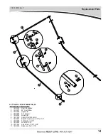
Page 16: ... 1808671 Spring Shaft 7 8 Hex x 14 1 4 11 1118955 Spring Retainer 12 1704476 Torsion Spring 2 3 4 OD Left Hand 13 1804477 Torsion Spring 2 3 4 OD Right Hand 14 1804139 Cap Screw 3 8 x 3 1 4 15 1800994 Flat Washer 3 8 16 1800993 Nylon Lock Nut 3 8 17 1808669 Spring Housing Base 1 2 3 4 5 6 7 8 17 6 1 2 11 12 10 1 9 14 15 16 15 14 5 13 4 3 SPRING PIVOT SUPPORTS TANDEM AXLES Item Part Description 1 1...

Page 17: ...1 1800300 Rear Crosspiece 2 1800597 90 Cast Elbow 3 1800548 Upper Arm 4 1800547 Arm Coupler 5 1800545 Lower Arm 6 1801636 Spring Pivot Connector 7 1800561 Pan Hd Cap Screw 5 16 x 2 1 4 8 1800989 Flat Washer 5 16 9 1800990 Lock Nut 5 16 10 1801025 Cap Screw 7 16 x 2 3 4 11 1800329 Nylon Lock Nut 7 16 9 8 7 6 10 11 ...

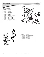
Page 18: ...1 9 1800787 Lock Washer 5 16 10 1800431 Hex Nut 5 16 11 1800430 Ring Terminal 8 Ga x 1 4 12 1801486 Ring Terminal 8 Ga x 3 8 13 1800417 Circuit Breaker 60 Amp 12V 14 1800441 Butt Connector 18 to 22 Ga 1 2 13 3 8 10 4 5 6 7 11 12 14 8 9 6 6 PIVOT ARM RESTS Item Part Description 1 1801012 Rubber Bumper 4 Drilled 2 1800140 Bumper Hold Down Bar 3 1801324 Pivot Arm Rest 4 1800972 Cap Screw 5 16 x 1 1 2...

Page 19: ...P N 1808922 Rev C 16 Notes ...

Page 20: ...s Arm Matic DuraPull Econo Pull Turbo Tarp2 2000 Series 5000 Series Hammer Bullet Flash Long Arm Waste Products SWAT The Ox Quick Flip III Sidewinder Sidewinder 350 HyTower SL HyTower DL Double Flip Donovan Belt Ratchet DBR ...

Reviews: