background image

74 

i n s t a l l a t i o n   o f   g a r a g e   a n d   i n d u s t r i a l   s e c t i o n a l   d o o r s

9

suPPLEmEnt

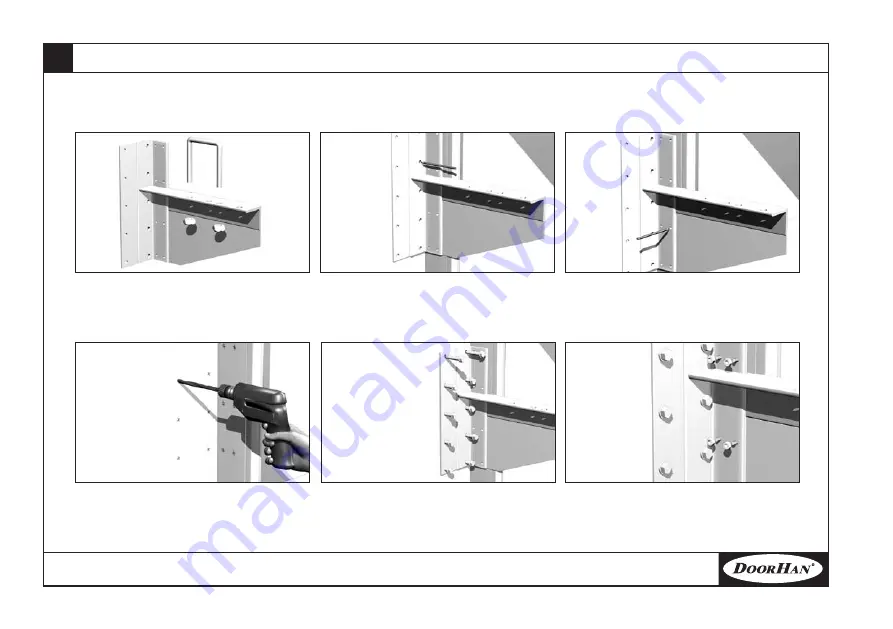
Mounting of the torsion gear with cylindrical shaft

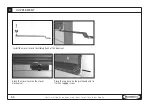
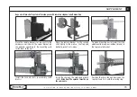
disassemble  the  remote  shaft  bracket  with 

a cramp

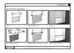
lean the remote bracket for the low shaft to the embrasure wall close to the corner support 

(on  the  outside)  according  to  the  mounting  card .  using  perforation  in  the  bracket  make 

marking for its fastening to the wall and the corner bracket .

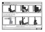
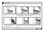
drill according to the marking 10 holes 

12 

mm  in  the  embrasure  wall  and  8  holes 

mm  in the corner support .

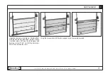
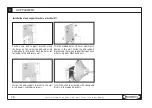
fasten the bracket to the wall using dowels and tapping screws and to the corner support 

using  bolted  joints .  install  the  second  bracket  on  other  side  of  the  embrasure  in  a  similar 

manner .

Summary of Contents for ISD01 Series

Page 1: ...Directions for installation of garage and industrial sectional doors 12 12 08...

Page 2: ...ng 23 Vertical tracks installation 23 Horizontal tracks installation 25 End U shaped support brackets installation 26 Cross bar sleeves installation 27 Panels installation 28 Torsion gear installation...

Page 3: ...shaft system on end support brackets 64 Two shaft system on U shaped end support brackets 67 Chain tension device installation 68 Mounting of torsion gear with remote octagonal shaft 70 Aspects of two...

Page 4: ...e and mounting recommendations of the directions ensure safe instal lation and operation of the equipment over a long period Do take safety measures while operating and mounting the equipment In case...

Page 5: ...without chain electric drive b1 and b2 distance between embrasure edge and side interior garage wall must not be less than 130 mm if with remote shaft 500 mm D garage depth distance between embrasure...

Page 6: ...250 mm and if the shaft is from below it must not be less than 500 mm While measuring following additional parameters must be taken into consideration Embrasure shape embrasure shape can be rectangula...

Page 7: ...ound practically for any premise Rigid framework made of galvanized steel ensures a long service life of the sectional doors protects from breaking H embrasure height 1 8 3 m B embrasure width 2 5 m h...

Page 8: ...atisfy more stringent requirements than standard garage doors do As a rule the industrial sectional doors are heavy constructions operated daily very strongly they are resistant to wind load and close...

Page 9: ...ildings with window fronts and shop windows motor shows exhibition and technical centers where interior must be seen through clear glasses H embrasure height from 2 m up to 8 m B embrasure width up to...

Page 10: ...ing different fastening ele ments can be used depending on embrasure material properties All fasteners must be resis tant to corrosion 1 Drill 2 Riveting tool 3 Measuring tape 5 m 4 Cross screwdriver...

Page 11: ...s t a l l a t i o n o f g a r a g e a n d i n d u s t r i a l s e c t i o n a l d o o r s 11 Sectional door shield System of guides and torsion gear 5 HARDWARE 1 18 21 20 19 4 14 7 7 3 6 9 24 5 2 16...

Page 12: ...assembly piece 3 Top panel 1 piece 6 Horizontal tracks in assembly 1 pair In this directions of sectional door mounting the doors with standard lift are taken as an example In supplement you can find...

Page 13: ...ith fastening 2 piece 7 Corner support in assembly with vertical track and side seal 1 pair 8 Installation profile 32x32x2 mm piece 10 Bolt for assembly of guides 1 4 3 4 piece 9 Multi purpose corner...

Page 14: ...n a l d o o r s 5 HARDWARE 18 Internal hinge piece 13 Set of cross bar sleeves 2 sets 14 Spring bumper 1 pair 15 Roller piece 16 Side support with roller holder piece 17 Top support with roller holder...

Page 15: ...step for industrial sectional doors 1 piece 19 Bottom corner bracket with wedge operated cable fastening 1 pair 20 Catch 1 piece quantity depends on door size installation depends on the door hardware...

Page 16: ...e c t i o n a l d o o r s 5 HARDWARE 32 Washer 8x24 piece 29 Lock plate piece 30 Tapping screw 8x70 mm piece 31 Dowel key PVC piece 27 Bolt with semi rounded head M8x25 piece 28 Flanged nut M8 piece q...

Page 17: ...a t i o n o f g a r a g e a n d i n d u s t r i a l s e c t i o n a l d o o r s 17 5 HARDWARE 33 Bushing key piece quantity depends on door size installation depends on the door hardware 34 Bushing fo...

Page 18: ...must be used If safety belt fastening to the construction parts is not possible safety rope extended behind construction parts in advance should be used In this case work must be performed by 3 erecto...

Page 19: ...contacts At work with such tools protective means rubber gloves and shoes must be worn Protective means must be tested in accordance with the current legislation Before start of work it is necessary...

Page 20: ...pports bottom parts The panel has operational opening for handle installation on industrial doors The middle panels are delivered as a unit of side caps riveted to the panel The panels have drilled ho...

Page 21: ...al hinges on ready made holes in the panel The holes in the bottom part of the hinge must index the holes in the panel made at plant Position the side caps on drilled openings using 4 tapping screw 6...

Page 22: ...panels Disconnect the roller holder from the side supports Install the side support on the drilled holes Install the internal hinges on the panel holes made at the manufacturing plant Holes in the bo...

Page 23: ...screws for panels Vertical tracks installation The vertical tracks are delivered in assembly with corner supports Before installation of the vertical tracks check floor horizontality For that place th...

Page 24: ...e installed in an embrasure so that its edges overlap the embrasure evenly on two sides Than install the vertical tracks on the panel The distance from the edge surface of the panel must be about 25 3...

Page 25: ...tion The horizontal tracks are delivered in assembly with a C profile to increase rigidity of the tracks The C profile and the horizontal tracks have the openings for fastening to the vertical tracks...

Page 26: ...tion in the bracket mark holes for fastening in the embrasure wall Drill the marked holes with a drill 12 mm Hammer in dowels in the wall Fix the bracket to the lintel using tapping screws do not tigh...

Page 27: ...MOUNTING Cross bar sleeve installation Cross bar sleeves are used to limit door leaf run along the embrasure plane Install the sleeves on the roller axis of the top supports Select and install cross b...

Page 28: ...he rollers with the roller holders on side supports Install the roller holders on the side supports Level the bottom panel with a builder s level If required use supports of a required thickness In ca...

Page 29: ...ents of the upper roller position to ensure the panels abutment on the embrasure Torsion gear installation Torsion gear is installed in the U shaped end support brackets and supported additionally wit...

Page 30: ...r Near Far Install the torsion gear in assembly so that the end plate with bushing is flush with the bracket s external wall Put on the shaft the closing ring it must abut on the bearing If the shaft...

Page 31: ...earing and installed end support U shaped brackets and the type of the drum is represented in the table 7 DOOR MOUNTING Fasten the spring failure safety device to the U shaped bracket using 2 sets of...

Page 32: ...rted in the special openings in the plug There is a special marking strip on the spring that indicates the amount of spring winds Design number of spring turns is indicated in the mounting card After...

Page 33: ...acket types depending on the lintel height and the door leaf dimensions Fastening with multi purpose corner brackets Fasten the bracket to the horizontal track with a lock plate a bolt and a nut Mark...

Page 34: ...Fix the mounting corner with tapping screws washers and dowels Check tracks horizontality using the builder s level If required correct the track s horizontality moving the holes in the punched angle...

Page 35: ...fastening free end of the cable using the cramp of fastening to the bracket s basis positioned on the elevated angle of the door leaf Remove the cramp Using a screwdriver lift a little the narrow end...

Page 36: ...sion adjustment by revolving of two parts of the shaft Fix the new position of the coupler with bolts and nuts Before making adjustment you need to ascertain that the floor is even without distortion...

Page 37: ...l l a t i o n o f g a r a g e a n d i n d u s t r i a l s e c t i o n a l d o o r s 37 7 DOOR MOUNTING Fasten the C profile to the horizontal tracks ends with lock plates bolts and nuts C profile ins...

Page 38: ...ing Before installation of the buffers unscrew bolts and nuts and fasten fastening cramps to the lock plates on the C profile using the bolts Install the buffers symmetrically relatively the embrasure...

Page 39: ...h other on different sides of the sandwich panel The handle for industrial doors is installed in a ready made opening in the bottom sandwich panel Insert 2 tapping screws on the external side of the d...

Page 40: ...o r s 7 DOOR MOUNTING Installation of protruding handle and light handle Mark the holes for the installation of the handle Drill 4 holes 10 12 mm After that fasten the handle with tapping screws 4 8...

Page 41: ...table height for opening Mark fastening holes Drill holes 4 2 mm for fastening of the catch and hole 15 in the corner support for wicket latch Fasten the catch to the panel using four tapping screws C...

Page 42: ...u open or close the doors manually do use the handle Do not apply force to open or to close the doors Jerky opening or closing of the doors is forbidden If automatic operator is used follow instructio...

Page 43: ...pports under mounting drivers insert the stopper in the plugs slots pull out the mounting driver Tighten the six sided screws for fastening the plugs to the shaft There is a special marking strip on t...

Page 44: ...th bolts 8 25 and nuts The torsion gear is installed in the end support brackets and is supported additionally by the internal bracket Installation of the torsion gear by using end support brackets In...

Page 45: ...ange with bolts 10 45 and nuts on the multi purpose internal bracket Run the cable through the special technological opening Tighten the squeezing screw that is fix the cable Run the cable through the...

Page 46: ...racket and coil it with the cable by the amount of the turns indicated in the mounting card Fasten the bracket to the shaft with the fastenings bolts RECOMMENDED In case of the adjustable connection c...

Page 47: ...d its cylinder Drill the marked holes 3 holes 5 5 mm for fastening of the lock under the lock handle and cylinder using the drill 19 mm The lock is recommended to be installed on the second panel from...

Page 48: ...fasten it to the lock housing using a screw Install the rod connecting the catch angle and the lock tongue After mounting check for the lock latch run smoothness and the catch functioning Install the...

Page 49: ...152 mm and 95 mm in internal diameter are used Install an additional bracket for double springs under 152 mm spring Mark the points for its fastening to the embrasure wall Fix the torsion gear on the...

Page 50: ...st the embrasure wall and mark the position of its fastening to the wall Fasten the spring failure safety device to the embrasure wall using tapping screws and washers Fasten the catch housing to the...

Page 51: ...he plates as a templet The cable safety device is installed on the door leaf like the bottom corner bracket with cable fine tuning with wedge operated cable fastening During installation of the corner...

Page 52: ...i o n a l d o o r s 9 SUPPLEMENT Cable break safety device While using the corner bracket with the cable break safety device mark and drill 6 holes 4 2 mm for bracket fastening Fix it with 6 tapping...

Page 53: ...nstallation of the bottom corner bracket with the cable tension device Put the bottom corner bracket for drum behind on the bottom panel mark and drill holes 4 2 mm for bracket fastening Fix the brack...

Page 54: ...plates and bolts the coupler Position the connection coupler on two parts of the shaft and fix it on operational openings using tapping screws for metal 6 3x25 for octagonal shaft If you are going to...

Page 55: ...the embrasure wall mark and drill holes 12 mm in the embrasure wall Insert dowels and fix the bracket with four tapping screws and washers Fix the adjustable bearing on the internal bracket using bolt...

Page 56: ...or on the right sides of the door Install on the shaft the manual chain operator having inserted the bushing key in the key slot before Put on the second closing ring Fix the closing rings on the shaf...

Page 57: ...ws and to the operator with washers and nuts Install the tension roller with the chain holder at 1 m height and on the same axis with the operator Mark and drill the holes in the wall for the tension...

Page 58: ...Place the tension roller on the floor on the same axis with the operator Mark and drill the holes in the floor for the tension roller fastening Insert the anchor bolts in the drilled holes and tighte...

Page 59: ...l s e c t i o n a l d o o r s 59 9 SUPPLEMENT If the door leaf has a wicket the wicket door closer must be installed Wicket door closer installation Position the door closer on 4 ready made holes Remo...

Page 60: ...n d i n d u s t r i a l s e c t i o n a l d o o r s Install the closer lever in the sliding trunk of the door leaf Block the closer lever on the closer mechanism Place the cap back on the profile end...

Page 61: ...or the shield reinforcement in both vertical and horizontal positions The Omega profile is recommended to be installed at one level with the side supports and to be fastened to the panel using rivets...

Page 62: ...n of halyard capronic One end of the halyard capronic fasten to the roller bushing on the bottom corner bracket The halyard capronic is used to close the door by hand if there is a high embrasure Fast...

Page 63: ...t r i a l s e c t i o n a l d o o r s 63 9 SUPPLEMENT Aspects of vertical and high lift installation High lift High lift with remote shaft Vertical lift Vertical lift with remote shaft High lift with...

Page 64: ...n the wall In a similar manner mark the holes for the bracket fastening on other side of the embrasure Install symmetrically on the inside the second support bracket for that position it to the embras...

Page 65: ...support bracket close to the wall so that vertically it is in one line with the bottom bracket fastened to the corner support and to the wall The center to center distance between the shafts A can var...

Page 66: ...ner install the sprocket and the chain on other side of the embrasure Install the additional support bracket on the bottom shaft for that position it to the embrasure wall mark and drill the holes for...

Page 67: ...o center distance between the shafts A is less than 393 mm shorten the chain according to the table Install the sprockets on other side of the embrasure in a similar manner Fix the sprockets using fas...

Page 68: ...device is used to tension the chain during its stretching and damping of the vibrations arising during its operation Position the tension device rollers on the outside of the chain Position the sprock...

Page 69: ...d i n d u s t r i a l s e c t i o n a l d o o r s 69 9 SUPPLEMENT hand hoist mounting jig To make easier the industrial sectional door torsion gear mounting we recommend to use the hand hoist and the...

Page 70: ...bracket make marking for its fastening to the wall Drill in the wall according to the marking 10 holes 12 mm and in the corner support 8 holes 7 mm Mounting of torsion gear with remote octagonal shaf...

Page 71: ...9 SUPPLEMENT Hook the shaft near the drums hitching them with the hand hoist load hook before it loose six sided screws 8X16 on the torsion gear end bushing for shaft 1 25 so that the bushing is able...

Page 72: ...u s t r i a l s e c t i o n a l d o o r s 9 SUPPLEMENT Install the torsion gear in the remote brackets slots positioning the end bushings Block the spring failure safety device Tighten the screws on...

Page 73: ...in the top remote bracket Position the chain tension device on the top shaft and fix it with the closing ring Install the second shaft in assembly with drums Install the chain on the sprockets of bot...

Page 74: ...wall close to the corner support on the outside according to the mounting card Using perforation in the bracket make marking for its fastening to the wall and the corner bracket Drill according to the...

Page 75: ...d in the mounting card and fix them using tapping screws for metal While mounting sectional doors with high vertical lift with drum below the cable supports must be installed on the bottom panel side...

Page 76: ...the corner support and using perforation in the bracket mark the holes for fastening to the embrasure wall Drill the marked holes 12 mm Hammer in dowels in the wall Fasten the end support bracket and...

Page 77: ...the drum from behind At vertical lift the bumper is installed on the vertical tracks Fasten the bumper to the C profile on the vertical track according to the figure Install the bumper so that when th...

Page 78: ...or door panels Position the support roller on the top horizontal track Loose the tapping screws adjust the upper supports to enable close abutment of the top panel to the lintel Tighten the tapping sc...

Page 79: ...be indexed Fasten the bracket to the wall using dowels and tapping screws and washers and to the bracket of pulley fastening and to the corner support using bolts and nuts Mark and drill the holes 12...

Page 80: ...cket to the ceiling with tapping screws 2 pieces and dowels If the lintel height is more than 400 mm the tracks are fastened using multi purpose corner brackets punched angle punched angle connectors...

Page 81: ...r s 81 9 SUPPLEMENT Installation of bumpers Mark and drill 2 holes 8 mm in the bottom horizontal tracks Fix the C profile using bolts with semi round head 8 25 and flanged nuts Fasten the spring bump...

Page 82: ...9 SUPPLEMENT Low lift drum from behind pulley installation Place the pulley along the holes in the corner bracket and fix it with 4 bolts with semi rounded head 8X16 Mark and drill a 8 mm hole in the...

Page 83: ...upport bracket for drum behind and safety device fastening bracket for drum behind fastening Fasten the assembled bracket to the double horizontal tracks using bolts 8X16 with semi round head and tigh...

Page 84: ...spring washer 10 Fasten the end plate with bearing to the end support bracket for drum from behind using 2 bolts with semi rounded head M8X16 fix the bolts on the close to the lintel or far from the l...

Page 85: ...e holes in the tracks for bracket fastening using perforation in it Drill the marked holes 8 5 mm Fasten the end support bracket to the double horizontal tracks using bolts and nuts Position and fix t...

Page 86: ...fastening bracket for drum behind on it before Fasten the fastening bracket for drum behind to the C profile using the C profile fastening bracket the mounting angle for horizontal lath installation...

Page 87: ...utral domestic detergents In case of door hinge creaking or roller axes creaking they should be lubricated through the lubrication hole in the central part of the hinge curl or in the central part of...

Page 88: ...88 i n s t a l l a t i o n o f g a r a g e a n d i n d u s t r i a l s e c t i o n a l d o o r s 10 NOTES...

Page 89: ...i n s t a l l a t i o n o f g a r a g e a n d i n d u s t r i a l s e c t i o n a l d o o r s 89 10 NOTES...

Page 90: ...90 i n s t a l l a t i o n o f g a r a g e a n d i n d u s t r i a l s e c t i o n a l d o o r s 10 NOTES...

Page 91: ...i n s t a l l a t i o n o f g a r a g e a n d i n d u s t r i a l s e c t i o n a l d o o r s 91 NOTES 10...

Page 92: ...121354 36 7 495 933 24 33 7 495 937 95 50 E mail info doorhan ru www doorhan ru...

Reviews: