


ON
1 2 3 4
1 2 3 4
5
6 7 8 9 10
115 V
A
C
INPUT
J1
P1
RESET
CLEAR
ST
A
T
AUTO OPEN
MOTOR DIR
AC ON ACT
LIMIT
TIMER
BA
TT ST
A
T
RUN
TIME
HEAR
T
BEA
T
TRICKLE
CHARGE
ST
A
T
SW2
ON
1473-010
REVERSE
SENSITIVITY
1601-010
TIME
DELAY
POWER
1
ON
2
3
4
5
6
7
8
1
ON
2
3
4
5
6
7
8
NC
UP
LOOP
DOWN
LOOP
1
2
3 4 5 6 7 8
9
10 11 12 13
14
SW 1
SW 2
LN
V
-
V
+
SUPPLY
GROUND
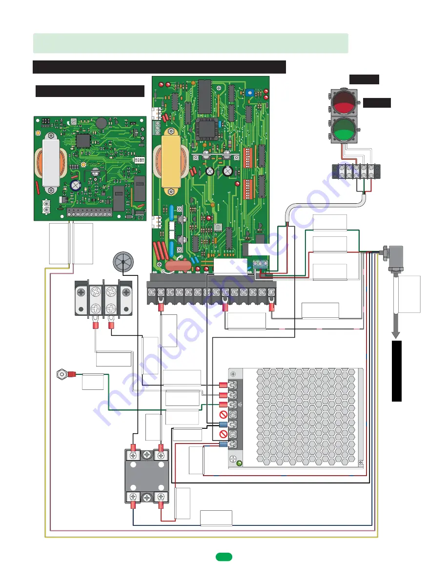
Required
MAKE SURE ALL POWER IS TURNED OFF TO OPERATOR!
OPTIONAL Convenience Open 1473
1601-426 Power Supply 8.
5
A
110V
AC HOT
Solid State Relay
L16
Terminal 2
Main PCB
110V
AC HOT L14
115V Neutral
Terminal Block 2 Position
L20
N - Neutral
Transformer 8.5 amp
L22
L - Line
Transformer 8.5 amp
L21
115V HOT
Te
rminal Block 2 Position
L19
Ground
Transformer 8.5 amp
L23
Ground
Panel Stud
L24
NEU HOT
N-Close
Main PCB
Red Light C1 L1
N-Open
Main PCB
Green Light C2 L2
Common
Main PCB
LED Light C10 L11
Terminal 14
Main PCB
Reverse Edge C4 L4
Terminal 1
Batter
y Backup PCB
Breakaway Sensor NC
C9 L15
Terminal 2
Batter
y Backup PCB
Breakaway Sensor NC
C8 L13
12V Negative (-)
Solid State Relay
C6 L6
12V Positive (+)
Solid State Relay
C3 L3
1
2
4
3
NEG
POS
Relay
NO
NC
C
V-
Transformer 8.5 amp
L18
V+
Tr
ansformer 8.5 amp
L17
Black
White
White
Pink
Blue
Black
Green
Green
Red/Blue
Grey/Pink
Grey
Red
Red
Yellow
Common
Main PCB
12V Neg C7 L12
Terminal 9
Main PCB
Reverse Edge C5 L5
Relay for
Breakaway
Sensors
NOTE:
Will
NOT
work with older model
2340-010 convienence open board
Traffic Light - Black
(to V+ Power Supply)
NO - Open
- Green
NC - Close
- Red
Traffic
Light
Terminal
Traffic Light Cable
Black
Red/
Brown
Green
Red
White
White
Optional
LED Traffic
Light Kit
Sold Separately
Only wire your existing
Optional
components
Arm Relay
Contacts
1601 Octagon Breakaway Arm - Wiring Operator
Remove existing wire
from Main PCB
Terminal 2
and connect it to
Relay #1
To
Arm
See previous page
DoorKing Part Number
1601-295
2
1
1601-356
Harness
8
1601-269-G-7-21


