1835-067-A-9-18
13
P2
12
34
5
6
7
8
9
10
11
12
13
14
16AC
16AC
BAT
1NO
13-Black
12-White
11-Green
14-Red
Black
White
Blue
Yellow
Green
Red
Not used
9-Black
8-White
7-Green
10-Red
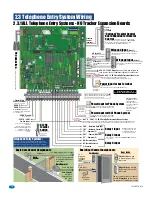
#7 thru #10
will activate
Relay 2
for its programmed strike time.
#11 thru #14
will activate
Relay 1
for its programmed strike time.
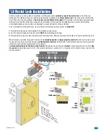
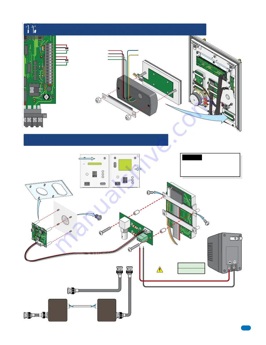
Install a OPTIONAL card reader as shown.
Remove and discard plate
from camera.
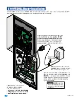
1.9 OPTIONAL Camera Kit Installation
P1
P2
+ -
BNC
Connector
CCTV Circuit
Board
Plastic
Spacer
Discard
existing
screw
.
Discard
existing
screw
.
Plastic
Spacer
Camera
Top
Power
Terminal
Lighted Keypad
Faceplate
Inside
Facepla
te
Remove
Plug from
faceplate
Existing Studs
Mount camera on existing studs
on the inside of the faceplate after
removing plate from camera.
Remove support bar from logo plate.
Card reader slides on existing stud
and is secured with support bar.
Mount CCTV circuit board on back
of lighted keypad as shown. Use
longer screws that comes with kit.
Polarity Matters!
16 AWG - 200 Ft
18 AWG - 100 Ft
Output
12 VDC
Power Wire Run
Black (-)
Red (+)
Wire not supplied
0
4
5
6
1
2
3
7
8
9
CALL
Z
A
0
4
5
6
1
2
3
7
8
9
CALL
Z
A
1835 Camera Position
1837 Camera Position
1.8 OPTIONAL Internal Card Reader Installation
Support Bar
Log
o Plate
Important:
DO NOT
power the
camera with the telephone entry
system’s 16.5 VAC 20 VA power
transformers.
Note:
Transformer
is for indoor use
and
MUST
be in a
protected enclosure
from weather when
using outdoors.
Internal Card Readers:
DoorKing DK Prox - P/N 1815-302
HID Prox Point Plus - P/N 1815-380
ID-Teck RF Tiny - P/N 1815-215
RG-59U Coax (Not supplied)
500 ft. max.
To Monitor, Video Recorder
CCTV Circuit Board Connections
To BNC
Connector
UTP wire
1400 ft. max.
To Monitor,
Video Recorder
DoorKing offers video adapters (Not supplied) for up to 1400 ft
using unshielded twisted pair telephone wire. (P/N 1812-039)
VTT-2000
Video
Adapter
(At Monitor,
Video
Recorder)
VTT-2000
Video
Adapter
(At 1830)
Install a OPTIONAL camera kit as shown (
P/N 1812-147).

