1835-067-A-9-18
49
This adjustment is located on the LCD interface board. This is adjusted at the factory and should
NOT
be
adjusted in the field.
4.3 Backlite Cutoff
3 2 1
BACKLITE
CUTOFF
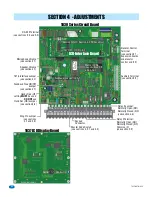
4.1 Speaker Volume, Microphone and Feedback
Speaker volume, microphone volume and feedback all interact with each other to affect the audio performance of the system.
1.
Locate the
speaker volume
,
microphone volume
and
feedback
adjustments on circuit board (see previous page).
2.
Set the
speaker volume
about 1/3 from full counter-clockwise.
3.
Set the
microphone volume
to 1/2.
4.
Place a phone call from the telephone entry system to a resident. If feedback occurs, turn the
speaker volume
counter-clockwise until it ceases.
5.
While the resident is still on the line, ask them to remain silent. Move the
feedback tone ON/OFF jumper
to to
the
ON
position. A tone will now be heard in the speaker. Rotate the
feedback
adjustment throughout its range
while listening to the sound coming from the speaker. When the sound is minimum, this is the correct setting.
Move
the
feedback tone ON/OFF jumper
back to to the
OFF
position.
6.
Speaker volume
and
microphone volume
may now be adjusted to desired levels. If both are set too loud,
feedback may result. For louder speaker volume, the microphone volume may need to be decreased. For louder
microphone volume, the speaker volume may need to be decreased.
7.
Normal setting for both
speaker volume
and
microphone volume
is about 1/2.
8.
After setting these adjustments, place some test calls. If feedback occurs, microphone and/or speaker volume
will need to be reduced.
MIC
VOL
3 2 1
FEED
BACK
3 2 1
3
2
1
SPK
VOL
LCD display is adjusted at the factory and should
NOT
need to be re-adjusted. If it does, Let the system run for at
least 10-minutes before making any display contrast adjustments.
4.2 LCD Display Contrast
This adjustment is located on the LCD interface board. Turn the contrast potentiometer clockwise to lighten,
counter-clockwise to darken until the display is satisfactory.
This adjustment is
only
located on back of the 1837 LCD display. Turn the contrast potentiometer clockwise to
lighten, counter-clockwise to darken until the display is satisfactory.
CONTRAST
3
1
TO
NE ON
TONE OFF
4.4 Master Code Switch
The master code switch
MUST
be kept in the
OFF
position for normal operation. Turn the master code
switch
ON
only when programming the system’s master code. See section 3.2.1 to program the system’s
master code. If the master code switch is
turned ON
and a new master code is
NOT
entered, the system will
sound a long tone after approximately 30 seconds. This tone will continue every 30 seconds until a new
master code is entered, or until the switch is turned off.
ON
OFF
MASTER
CODE
CONTRAST
3
1

