9150-065-Y-12-20
2
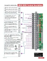
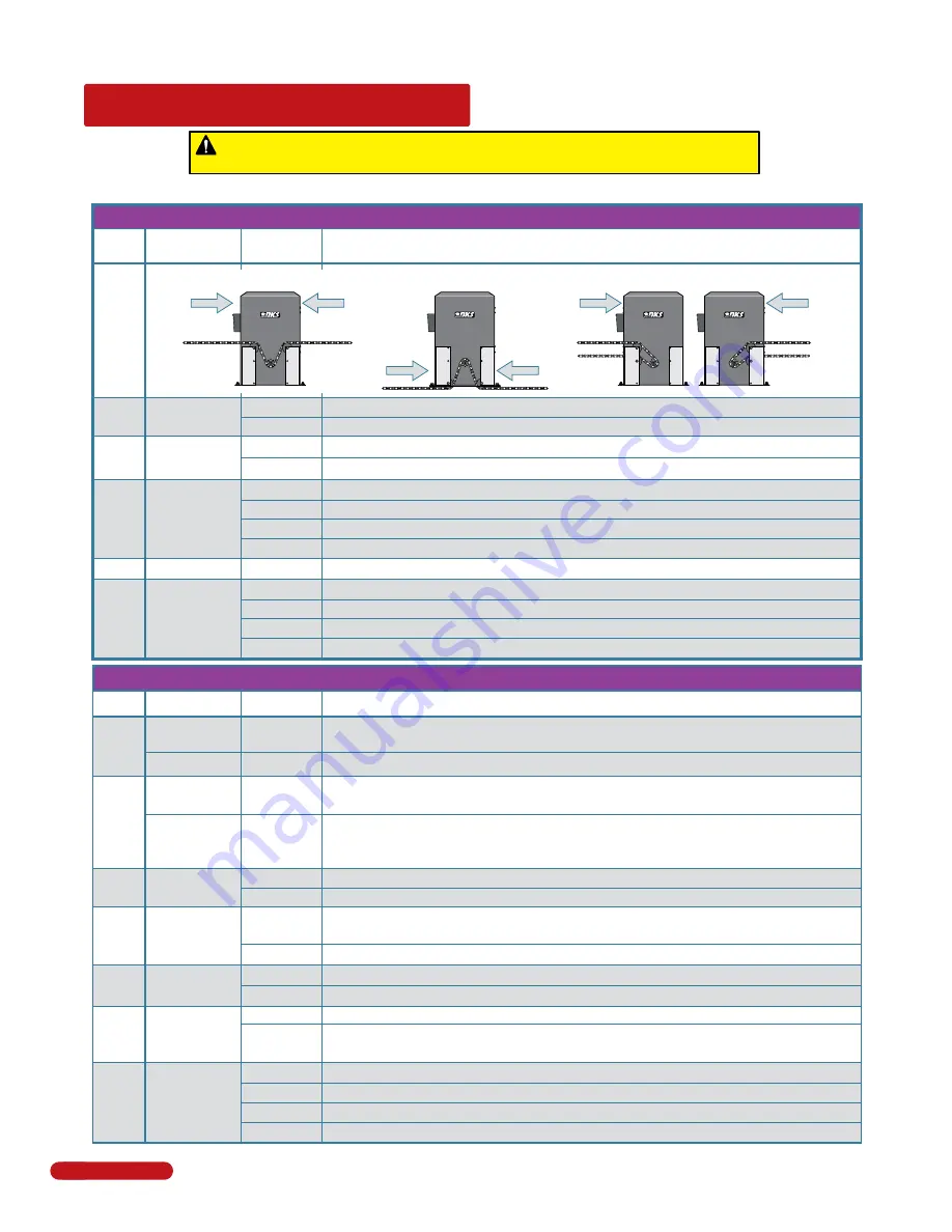
QUICK GUIDE: DIP-Switches
See page 21 & 22 for more info about DIP-switches.
7-OFF
7-OFF
7-ON
7-ON
8-OFF
8-ON
8-OFF
8-ON
Gate
Open
Back-Off
Position
Normal Setting.
Gate fully opens.
Gate stops short 1” from full open position. Used for a reversing edge device.
Gate stops short 2” from full open position. Used for a reversing edge device.
Gate stops short 3” from full open position. Used for a reversing edge device.
Switch
Function
Setting
Description
SW 1 (Left 8 Switches)
OFF
ON
4-OFF
4-OFF
4-ON
4-ON
5-OFF
5-ON
5-OFF
5-ON
Auto-Close
Timer
Relay Activation
and
LED Indicator
Light Activation
2
1
Motor
Hold
OFF
ON
3
4 and 5
7 and 8
Normal Setting.
No voltage to motor when gate is stopped (Level gate).
Voltage applied to motor always. Keeps inclined gate from coasting when stopped.
Auto-close timer is OFF. Manual input required to close gate.
Auto-close timer is ON. Adjustable from 1-23 seconds to close gate.
OFF
Not Used
6
Leave on OFF settng.
Relay activates and LED is ON when the gate is fully open.
Relay activates and LED is ON when the gate is not closed.
Relay activates and LED is ON when the gate is opening and open.
Relay activates and LED is ON when the gate is opening and closing.
Changes the direction the operator will open/close the gate depending on the different chain configurations.
Opening
direction
using
OFF
setting.
Opening
direction
using
ON
setting.
Post
Mounts
Center or
Opens
with
ON
setting.
Mounts
Right
All Rear
Opens
with
OFF
setting.
Mounts
Left
All Rear
Opening
direction
using
ON
setting.
Opening
direction
using
OFF
setting.
Mount
Front
OFF
ON
Operator Model
Select
5
7-OFF
7-OFF
7-ON
7-ON
8-OFF
8-ON
8-OFF
8-ON
Gate
Close
Back-Off
Position
Normal Setting.
Gate fully closes.
Gate stops short 1” from full close position. Used for a reversing edge device.
Gate stops short 2” from full close position. Used for a reversing edge device.
Gate stops short 3” from full close position. Used for a reversing edge device.
Switch
Function
Setting
Description
SW 2 (Right 8 Switches)
2
7 and 8
Built-in
Solenoid
Lock
OFF
ON
4
Normal Setting.
Fail-safe logic. Lock engages only if attempt is made to force gate open (Factory
setup).
Fail-secure logic. Lock engages after each gate cycle (2600-865 Lock kit required).
Normal Setting.
Switch must be OFF for Model 9150.
DO NOT
use ON setting for Model 9150.
OFF
ON
Partial Open
(14 Ft)
3
Normal Setting.
Switch must be OFF for terminal #5 input to open gate 14 Ft.
DO NOT
use ON setting.
NOT
associated with partial open feature for the 9150.
OFF
ON
Normal Setting.
Input to terminal #6 and/or reverse loops will
reverse
gate
during
close
cycle.
Input to terminal #6 and/or reverse loops will
stop
gate during
close
cycle – gate
will continue to close after input to terminal #6 and/or reverse loops are cleared
(Helps prevent tailgating vehicles from unauthorized entry).
OFF
ON
6
Normal Setting.
Timer will function normally.
Opening gate will stop and begin to close as soon as all reversing inputs (Reverse loops, photo
sensors) are cleared regardless of the distance the gate has opened.
1
Quick-Close
Timer Override
Exit Loop Port
Output
Full Open Input
Reverses Gate
Stops Gate
Whenever a switch setting is changed, power MUST be cycled to the operator.
Every time
the operator is powered up, the
First
open command will automatically run “
Multiple
gate cycles”
that will locate and remember the gate’s open and close positions (See page 23).
OFF
ON
Switches logic level output of
EXIT loop port
to main terminal #10.
Normal Setting.
Plug-in exit loop detector will fully open gate (Single operator).
Quick Guide - 1


