background image

 9150-065-Y-12-20

1

8

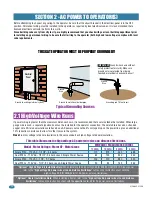
2.1 High Voltage Wire Runs

This table illustrates the high voltage AC power wire size and distance limitations.

Model - Motor Voltage - Motor HP - Motor Amps

Wire Size / Max Distance in Feet

170

275

460

685

85

135

230

340

12 AWG

10 AWG

8 AWG

6 AWG

Single 9150 - 115 VAC - 1/2 HP - 5.4 Amps
Dual 9150s - 115 VAC - 1/2 HP - 5.4 Amps each, Single Power Source

Single 9150 - 115 VAC - 1 HP - 9.7 Amps
Dual 9150s - 115 VAC - 1 HP - 9.7 Amps each, Single Power Source

100

170

280

520

50

85

140

260

SECTION 2 - AC POWER TO OPERATOR(S)

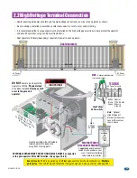
Before attempting to connect any wiring to the operator, be sure that the circuit breaker in the electrical panel is in the OFF 
position. Permanent wiring must be installed to the operator as required by local electrical codes. It is recommended that a 
licensed electrical contractor perform this work. 

Since building codes vary from city to city, we highly recommend that you check with your local building department prior 
to installing any permanent wiring to be sure that all wiring to the operator (both high and low voltage) complies with local 
code requirements.

THIS GATE OPERATOR MUST BE PROPERLY GROUNDED!!

If power wiring is greater than the maximum distance shown, it is recommended that a service feeder be installed. When large 
gauge wire is used, a separate junction box must be installed for the operator connection. The wire table is based on stranded 
copper wire. Wire run calculations are based on a AC power source with a 3% voltage drop on the power line, plus an additional 
10% reduction in distance to allow for other losses in the system.

Never


run low voltage rated wire insulation in the same conduit as high voltage rated wire insulation.

Typical Grounding Sources

Ground to metallic cold water pipe.

Ground

Wire

Ground

Wire

Ground to existing electrical system.

Electrical

Panel

Grounding rod 10 feet in soil.

IMPORTANT:

 Ground wire shown without 

safety protection for clarity. Make sure 
ground wire is protected from being 
touched or electrical shock could occur!

“Optional” Heater Installation Note:

 When installing a heater, refer to the 

“high voltage AC power wire size and distance 

limitations”

 table on the instruction sheet with the 

specific

 heater kit for AC power wire run limitations. 

“Optional” High Voltage Kit Installation Note:

 When installing the high voltage kit for 208/230/460/575 VAC input power, 

refer to the 

“high voltage AC power wire size and distance limitations”

 table on the instruction sheet with the

high voltage kit (P/N 2600-266) for AC power wire run limitations. 

Summary of Contents for 9150 Series

Page 1: ...wh ile gat e is mo vin g Re ad ow ner s ma nua l and saf ety ins tru ctio ns SE RI OU S IN JU RY OR DE AT H CL AS S CE RT IFI ED TO CA N C SA C2 2 2 NO 24 7 CO NF OR MS TO AN SI UL 32 5 VE HI CU LA R...

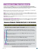
Page 2: ...sition Normal Setting Gate fully closes Gate stops short 1 from full close position Used for a reversing edge device Gate stops short 2 from full close position Used for a reversing edge device Gate s...

Page 3: ...N input will re set and hold timer When gate is open auto close timer SW 1 switch 2 is turned OFF input will prevent gate from closing When gate is closing input will stop gate when SW 2 switch 2 is O...

Page 4: ...e right to make changes in the products described in this manual without notice and without obligation of DoorKing Inc to notify any persons of any such revisions or changes Additionally DoorKing Inc...

Page 5: ...OF GATE OPERATOR 45 8 1 Alarm Sounding OR Chirping and Gate WILL NOT Operate 8 2 Manual Gate Operation 8 3 Gate Operators Monthly Checkup 8 4 New Installation Checklist for Installer and Property Owne...

Page 6: ...e to 2 1 4 inches or less Install a contact sensor in this area for safety See on next page and page 26 A gap measured in the horizontal plane parallel to the roadway between a fixed stationary object...

Page 7: ...ns Non Contact Sensors Photo Sensors 1 2 Entrapment protection devices are required to reduce the risk of injury Install sensors where the risk of entrapment or obstruction exists while gate is moving...

Page 8: ...reduce reversing sensitivity to compensate for a damaged gate For gate operators utilizing Type D protection 1 The gate operator controls must be placed so that the user has full view of the gate area...

Page 9: ...s are installed a minimum distance of 6 feet away from the gate and gate operator or in such a way that a person cannot touch the gate or gate operator while using the device If access control devices...

Page 10: ...Inherent entrapment protection system Type B1 Non contact sensor photoelectric sensor or the equivalent Type B2 Contact sensor edge device or equivalent Type C Inherent force limiting inherent adjust...

Page 11: ...for vehicular traffic flow at entrances or exits to areas such as parking garages lots or toll areas VEHICULAR HORIZONTAL SLIDE GATE OPERATOR OR SYSTEM A vehicular gate operator or system that control...

Page 12: ...ops Gate End Retainer Helps stabilize the end of the gate in the open or closed position Recommended for all slide gate applications Endless Idler Assembly with Protective Cover Helps to minimize a pi...

Page 13: ...CSA C22 2 NO 247 CONFORMS TO ANSI UL 325 VEHICULAR GATE OPERATOR HP 53382 MODEL SERIAL VOLTS PHASE AMPS 60 Hz MAX GATE LOAD DoorKing Inc Inglewood CA WARN ING MOVING GATE CAN CAUSE Operate gate only w...

Page 14: ...l stop for the gate Both are shown only one type is needed Base Plate Stop Bracket Chain Setup Chain Setup The Model 9150 operator is designed to be installed in the front rear center or ceiling mount...

Page 15: ...oorKing Rear Position with Concrete Pad Hides the chain from outside the property looking in Chain setup is the same as above Rear Position with Post Mount Hides the chain from outside the property lo...

Page 16: ...roperty looking in Optional chain tray kit can be used and is recommended for gates over 20 ft supports the chain s weight and helps prevent chain stretching See page 17 for more information Note Chai...

Page 17: ...r and Communication wires Loop Lead In Wires Low Voltage wire insulation AC Input Power High Voltage wire insulation AC Input Power High Voltage wire insulation 3 4 Inch Conduit Recommended The condui...

Page 18: ...e Weld the posts to the base plate and mount assembly into concrete BEFORE attaching the operator Conduit runs up through 6 x 6 steel posts Note Operator must be mounted 1 min away from gate Low Volt...

Page 19: ...et Lines up with Idler Wheels Correct Chain Bracket Height Correct Chain Bracket Height Chain brackets positioned too low NO NO NO NO Chain Idler Wheels 1 minimum from operator housing to gate YES YES...

Page 20: ...wheel wear and chain stretching Lower chain MUST align with upper chain Upper and lower chain MUST be the same height as they are on the operator idler wheels NO NO NO Gate Rail Gate Rail Chain Bracke...

Page 21: ...he chain DoorKing offers a chain tray kit in sections to fit any length gate DoorKing P N 2601 270 10 Ft section Chain Tray Supporting Bracket Facing down Chain Tray Supporting Bracket Facing up Weep...

Page 22: ...han the maximum distance shown it is recommended that a service feeder be installed When large gauge wire is used a separate junction box must be installed for the operator connection The wire table i...

Page 23: ...e with local codes Be sure to color code all wiring It is recommended that a surge suppressor be installed on the high voltage power lines to help protect the operator and circuit board from surges an...

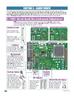
Page 24: ...Detector Single Channel Loop Detector Dry Relay Contact N C N O Set the DIP switches on the circuit board to the desired setting See switch setting charts on next 2 pages DIP Switches ON 1 2 3 4 5 6 7...

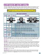
Page 25: ...g on a green light when the gate is full open If a magnetic lock is used with the gate operator these switches must be set for magnetic lock operation which limits the relay to activate only when the...

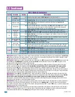
Page 26: ...orized entry If switch 2 is turned OFF Reverse the closing gate that gets activated by a tailgating vehicle will reverse back to the open position possibly allowing the tailgating vehicle unauthorized...

Page 27: ...powered up the first open command will automatically run Multiple gate cycles that will locate and remember the gate s open and close positions These positions are determined by the physical stops th...

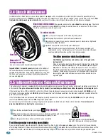
Page 28: ...est the operator reversing sensitivity Press the Key Switch button to cycle the gate While gate is cycling slowly rotate reverse sensor clockwise until the gate reverses direction Rotate reverse senso...

Page 29: ...ov ing Read own er s man ual and safet y instr uctio ns SER IOU S INJ UR Y OR DE ATH CLA SS CER TIFI ED TO CAN CSA C22 2 NO 247 CON FOR MS TO ANS I UL 325 VEH ICU LAR GAT E OPE RAT OR HP 53382 MOD EL...

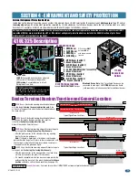
Page 30: ...am 3 OPEN Edge 4 CLOSE Edge Only 1 monitored Device can be connected to each input An OPTIONAL Expansion Kit sold separately will allow connection for additional devices 1 OPEN Beam Switch 1 2 Ground...

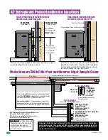
Page 31: ...ged into the built in convenience outlets located on the operator See page 25 See pages 2 and 26 for gate gap area and filler post information Open Beam Receiver MUST monitor for the presence of the t...

Page 32: ...PE LEARN INPUT OUTPUT ASSIGNMENTS ON 1 2 3 4 5 6 A B X X 3 4 5 6 Model MIM 62 Class 2 Device Set to R Set 3 to A Output Set 4 to OFF See manufacturer s manual to LEARN open edges See manufacturer s ma...

Page 33: ...E Beam 3 OPEN Edge 4 CLOSE Edge DIP switches MUST be turned ON for each device wired to terminal Wire Mesh CLOSE Beam photocell CLOSE Beam photocell A wide gate will not be protected from obstructions...

Page 34: ...ns the gate for exiting vehicles without having to use a transmitter or keypad The exit loop can be placed a minimum of 4 feet away from the reverse loop or far enough away from the gate so the gate h...

Page 35: ...ON input will re set and hold timer When gate is open auto close timer SW 1 switch 2 is turned OFF input will prevent gate from closing When gate is closing input will stop gate when SW 2 switch 2 is...

Page 36: ...to the partial open 14 ft setting External entrapment protection devices will also open the gate to the partial open setting If the Inherent Reverse Sensor gets activated during the close cycle it wil...

Page 37: ...nputs loop detector problems any forced entry attempts if the gate has struck anything during the open or close cycle power interruptions etc For more detailed information refer to the Tracker Install...

Page 38: ...wired in parallel between primary and secondary operators SW 2 switch 1 must be OFF Plug into Primary Operator Exit Loop Port Dual Channel 9409 Automatic Exit Loop Reverse Loop Reverse Loop LL OPE LL...

Page 39: ...with a rigid object or stop or reverse when an object activates the non contact sensors After adjusting the force or the limit of travel retest the gate operator Failure to adjust and retest the gate...

Page 40: ...gate will reverse and run back to the closed position The time clock input is still present but the gate will not re open Example 2 If the gate is closing and an entrapment protection device is activa...

Page 41: ...D that power to the operator has been SHUT OFF Solenoid Lock Clutch Plate SW 2 switch 4 must be OFF ON 1 2 3 4 5 6 7 8 SW 2 Note DoorKing operators have a built in alarm reset push button mounted on t...

Page 42: ...bs truc tion s Do not allow child ren to play in gate area or ope rate gate Do not stan d in gate path or walk thro ugh path whil e gate is mov ing Rea d own er s man ual and safe ty inst ruct ions SE...

Page 43: ...hen an obstruction is encountered Check for alignment tightness and wear Check vehicular exit and reverse loops for proper operation Check manual release for proper operation See page 46 Pulleys Check...

Page 44: ...gh voltage supply A voltage drop on the supply line usually caused by using too small supply voltage wires will cause the operator to malfunction Refer to the wire size chart in section 2 1 on page 18...

Page 45: ...om excess wires can diminish magnetic field Check that the magnetic pickup transistors on control board are within 1 8 inch of the clear plastic protective cover above the black plastic magnetic sprin...

Page 46: ...ntains all the necessary wires to interconnect primary secondary operators Cable length 30 ft P N 2600 755 40 ft P N 2600 756 50 ft P N 2600 757 Time Clock 7 day time clock can be used to automaticall...

Page 47: ...6 5 4 3 2 1 Brown White White Green Black Black White White Black White White Loop Yellow Red Red Yellow White Chassis Ground Board Ground Convenience Outlets Power Neutral Model 9150 1 2 HP 115 VAC...

Page 48: ...ellow White Reset Button AC Power Switch MOV Assembly Brown White White Green Black Black White White Black Red Yellow White Chassis Ground Board Ground Convenience Outlets Motor Resistors Power Neutr...

Page 49: ...mpletes the reverse cycle the inherent entrapment protection system Type A gets activated If a Fire Dept Access Device has been activated by emergency personnel then operator can be reset and put back...

Page 50: ...ONS for more information about operating this gate operator Gate CANNOT be manually PUSHED open until FAIL SECURE Lock has been UNLOCKED WARNIN G MOV IN G GA TE CA N CA US E Ope rate gat e onl y whe n...

Page 51: ...the gate will resume opening when the beam is clear If gate does NOT respond like it should in either direction of gate travel contact a trained service technician to make adjustments or repairs Test...

Page 52: ...installer AND property owner If it is not applicable enter N A Please note that the checklist is intended to be a summary of many important automated vehicular gate aspects But may not inclusively id...

Page 53: ...STRUCTIONS for more information about operating this gate operator When Alarm is Sounding OR Chirping Operator is in a HARD Shutdown Condition The alarm will sound for 5 five minutes After five minute...

Page 54: ...25 August 2018 Standard Entrapment Protection must be provided for the gate system where the risk of entrapment or obstruction exists The operator will NOT run without one or more monitored type B1 or...

Reviews: