9150-065-Y-12-20
22
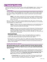
3.2 Continued
OFF
ON
Operator Model
Select
5
7-OFF
7-OFF
7-ON
7-ON
8-OFF
8-ON
8-OFF
8-ON
Gate
Close
Back-Off
Position
Normal Setting.
Gate fully closes.
Gate stops short 1” from full close position. Used for a reversing edge device.
Gate stops short 2” from full close position. Used for a reversing edge device.
Gate stops short 3” from full close position. Used for a reversing edge device.
Switch
Function
Setting
Description
SW 2 (Right 8 Switches)
2
7 and 8
Built-in
Solenoid
Lock
OFF
ON
4
Normal Setting.
Fail-safe logic. Lock engages only if attempt is made to force gate
open (Factory setup).
Fail-secure logic. Lock engages after each gate cycle (2600-865 Lock kit required).
Normal Setting.
Switch must be OFF for Model 9150.
DO NOT
use ON setting for Model 9150.
OFF
ON
Partial Open
(14 Ft)
3
Normal Setting.
Switch must be OFF for terminal #5 input to open gate 14 Ft.
DO NOT
use ON setting.
NOT
associated with partial open feature for the 9150.
OFF
ON
Normal Setting.
Input to terminal #6 and/or reverse loops will
reverse
gate
during
close
cycle.
Input to terminal #6 and/or reverse loops will
stop
gate during
close
cycle – gate
will continue to close after input to terminal #6 and/or reverse loops are cleared
(Helps prevent tailgating vehicles from unauthorized entry).
OFF
ON
6
Normal Setting.
Timer will function normally.
Opening gate will stop and begin to close as soon as all reversing inputs (Reverse
loops, photo sensors) are cleared regardless of the distance the gate has opened.
1
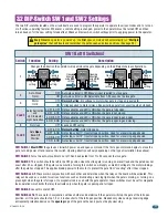
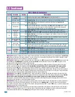
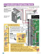
SW 2 Switch 1
Switch 1 Determines if the output of the loop detector (DoorKing loop detectors only) plugged into the
EXIT loop
port
will be sent directly to the microprocessor to open (or reverse a closing gate) the gate,
or
if the output is directed to Main
Terminal #10 where it can be connected to other input terminals.
SW 2 Switch 2
Determines if an input to terminal #6 (N.O. Photo Sensors,
NOT
entrapment protection)
AND/OR
reverse loops will
reverse
OR
stop a
CLOSING gate
. A tailgating vehicle
can activate
terminal #6 and/or reverse loops
while
the gate is in the
closing cycle from the previous vehicle’s authorized entry:
If
switch 2 is turned
OFF
(Reverse), the closing gate that gets activated by a tailgating vehicle will reverse back to the open
position, possibly allowing the tailgating vehicle
unauthorized entry while the gate is reversing back to the open position
.
If
switch 2 is turned
ON
(Stop), the closing gate that gets activated by a tailgating vehicle will stop, partially or completely
blocking the pathway,
NOT
allowing the tailgating vehicle to enter without proper authorization. The gate will not move until all
sensors are clear, usually forcing the tailgating vehicle that activated the sensors to back away from the gate. The gate will then
continue until closed, helping prevent the tailgating vehicle from unauthorized entry.
SW 2 Switch 3
Switch
must
be in the
OFF
position. Inputs connected to terminal #5 will open and reverse the gate only 14 Ft.
SW 2 Switch 4
This switch determines the operation of the built-in solenoid lock. The OFF setting is the factory setup.
Caution:
Do not set this switch to ON unless the 2600-865 fail-secure manual release kit has been installed in the operator.
Changing this switch to the ON setting without installing the lock kit will damage the operator. See pages 36 and 37 for more
information about Fail-Safe vs. Fail-Secure release systems.
SW 2 Switch 6
Turning the quick-close feature on will cause the auto-close timer to close the gate after 1 second, regardless of
the setting of the auto-close timer potentiometer. This will also cause an
opening gate
to stop and reverse when the reverse
loops and/or N.O. photo sensors are cleared. This feature, along with turning SW 2, switch 2
ON
above, is useful to help prevent
tailgating vehicles from unauthorized entry.
SW 2 Switches 7-8
These work in conjunction with each other and determine if the operator will stop the gate at the full close
position, or if the gate should stop 1, 2 or 3 inches short of the full close position. Needed only when using a reversing edge
entrapment protection device on the
closing
edge of the gate with an end post as the physical stop.
Quick-Close
Timer Override
Exit Loop Port
Output
Full Open Input
Reverses Gate
Stops Gate
OFF
ON
Switches logic level output of
EXIT loop port
to main terminal #10.
Normal Setting.
Plug-in exit loop detector will fully open gate (Single operator).

