9150-065-Y-12-20
2
8
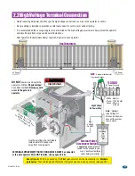
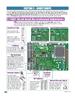
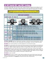
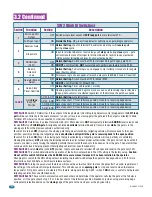
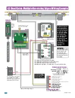
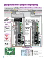
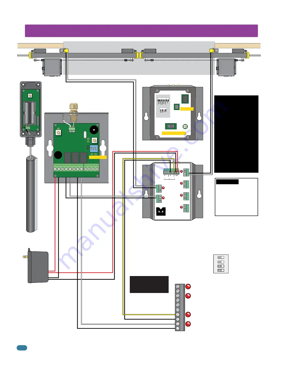
4.3 Dual Gates Multiple Reversing Edges Wiring Sample
2 Wire T2 T
ermination 10K Edge
Wireless Edge
Transmitter
Wireless Edge
Transmitter
Wireless Edge
Transmitter
Wireless Edge
Transmitter
PROG
RB-TX10
COM
P/N.C.
10K
COM
P/N.C.
10K
POWER
Output B
Output A
IN3
MIM-62
Multi-Input Module
IN1
Miller
Edge
IN4
IN5
IN6
Input
Com
Pwr+
Pwr-
IN2
Input
Com
Pwr+
Pwr-
Pwr+
Pwr-
Input
Com
Pwr+
Pwr-
Input
Com
Pwr+
Pwr-
Input
Com
Pwr+
Pwr-
Input
Com
Wall / Fence
Wireless Open Edge
Wireless Close Edge
Filler Post
Open Edge
Wall / Fence
Wireless Open Edge
Wireless Close Edge
Filler Post
Open Edge
Gate Link
MIM-62 Front
Wireless Edge
Transmitter
MIM-62 Back
HARDWired
HARDWired
Power
Output A
Power
Wireless OPEN
Edges (Relay 1)
P/N - 8080-079 Multi-Input Module (MIM-62)
P/N - 8080-008 RF Monitored Gate Link Kit (RB-G-K10)
P/N - 8080-006 Monitored Transmitter RB-TX-10
Miller Edge Sensing Edges - All models with a T2 (resistive) termination.
Wireless CLOSE Edges (Relay 2)
ON DIP
1 2 3 4
+
CS1
GND ANT
PROG
C1 BS1
BS2
NO3 C3
ATEST
Com
CS2
C2
-
R3
R1
R2
MR
ATEST
CHECK
12/24 AC/DC
POWER
COM
P/N.C.
10K
COM
P/N.C.
10K
PWR (+)
PWR (-)
INPUT (-)
INPUT (+)
OUT B
OUT A
WIRING DIAGRAM
P
R
OUT A
OUT B
1 2
ON
OUTPUT
TYPE
LEARN
INPUT/OUTPUT
ASSIGNMENTS
ON
1 2 3 4 5 6
A
B
X X 3 4 5 6
Model # MIM-62 Class 2 Device
Set to “R”
Set 3 to “A Output”
Set 4 to “OFF”
See manufacturer’s
manual to “LEARN”
open edges.
See manufacturer’s manual
to “PROG”
wireless edges.
Mount
on gate
next to
edge.
All safety devices
MUST
be wired to the
PRIMARY
operator
ONLY
when
using dual gate operators.
PRIMARY UL 325 DIP-Switches
DIP-switches
3 and 4 ON
1
ON
2
3
4
PRIMARY UL 325 Terminal
Connect
ONLY MONITORED
Devices
1 - OPEN Beam
2 - CLOSE Beam
3 - OPEN Edge
4 - CLOSE Edge
1 - OPEN Beam (Switch 1)
2 - Ground (Common)
3 - CLOSE Beam (Switch 2)
4 - Ground (Common)
5 - 24 VAC 250 mA Max (Don’t exceed this)
6 - Ground (Common)
7 - OPEN Edge (Switch 3)
8 - Ground (Common)
9 - CLOSE Edge (Switch 4)
10 - Ground (Common)
DIP-switches
MUST
be turned
ON
for each device wired to terminal.
1
2
3
4
5
6
7
8
9
10
Use a 24 VDC power transformer
(not supplied) or (U.L. listed
equivalent) to power the MIM-62
and Gate Link. (P/N 1812-136)
24 VDC
IMPORTANT:
Monitored
Photo and Edge sensors
must be end-of-line
resistive types. See
specific manufacturer's
wiring manual for more
information.
Entrapment Protection
must be provided for
the gate system where
the risk of entrapment
or obstruction exists.
The operator will NOT
run without ONE or
more monitored type
B1 or B2 external
entrapment protection
devices in EACH
direction of gate travel
(minimum of 2
external devices
required).

