9150-065-Y-12-20
29
OPEN
Beam (photocell)
OPEN
Beam (photocell)
MIM-62 (Sold Separately)
COM
P/N.C.
10K
COM
P/N.C.
10K
POWER
Output B
Output A
IN3
MIM-62
Multi-Input Module
IN1
Miller
Edge
IN4
IN5
IN6
Input
Com
Pwr+
Pwr
-
IN2
Input
Com
Pwr+
Pwr
-
Pwr+
Pwr
-
Input
Com
Pwr+
Pwr
-
Input
Com
Pwr+
Pwr
-
Input
Com
Pwr+
Pwr
-
Input
Com
Power
Power
Power
#3 - Close Beam
#1 - Open Beam
Output A
(P/N.C.)
IN1
and
IN2
Output B
(P/N.C.)
IN3
and
IN4
POWER
COM
P/N.C.
10K
COM
P/N.C.
10K
PWR (+)
PWR (-)
INPUT (-)
INPUT (+)
OUT B
OUT A
WIRING DIAGRAM
P
R
OUT A
OUT B
12
ON
OUTPUT
TYPE
LEARN
INPUT/OUTPUT
ASSIGNMENTS
ON
1
2
3
4
5
6
A
B
X X 3 4 5 6
Model # MIM-62 Class 2 Device
Set both to
“P” Pulse
Set 3 & 4
to “B”
IMPORTANT:
All
normally closed (NC)
inputs
must
use power from MIM-62.
75 mA maximum per channel.
Use a 24 VDC power
transformer
(not supplied) or (U.L.
listed equivalent) to
power the MIM-62.
(P/N 1812-136)
24 VDC
Up to 6 photocells can be added.
See manufacturer’s manual to add
and “LEARN” additional photocells
if needed.
Front
Back
Power
Wide Gate
Section
IN1 & IN2 to
Output A
ONLY
.
IN1
IN1
IN2
IN2
IN4
IN3
IN4
IN3
Box Frame Type Gate
All safety devices
MUST
be wired to the
PRIMARY
operator
ONLY
when using dual gate operators.
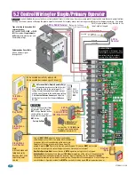
PRIMARY UL 325 Terminal
Connect
ONLY MONITORED
Devices
1 - OPEN Beam (Switch 1)
2 - Ground (Common)
3 - CLOSE Beam (Switch 2)
4 - Ground (Common)
5 - 24 VAC 250 mA Max (Don’t exceed this)
6 - Ground (Common)
7 - OPEN Edge (Switch 3)
8 - Ground (Common)
9 - CLOSE Edge (Switch 4)
10 - Ground (Common)
1
2
3
4
5
6
7
8
9
10
PRIMARY UL 325 DIP-Switches
DIP-switches
1 and 2 ON
1
ON
2
3
4
1 - OPEN Beam
2 - CLOSE Beam
3 - OPEN Edge
4 - CLOSE Edge
DIP-switches
MUST
be turned
ON
for each device wired to terminal.
Wire
Mesh
CLOSE
Beam (photocell)
CLOSE
Beam (photocell)
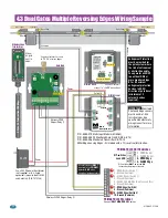
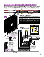
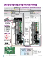
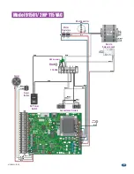
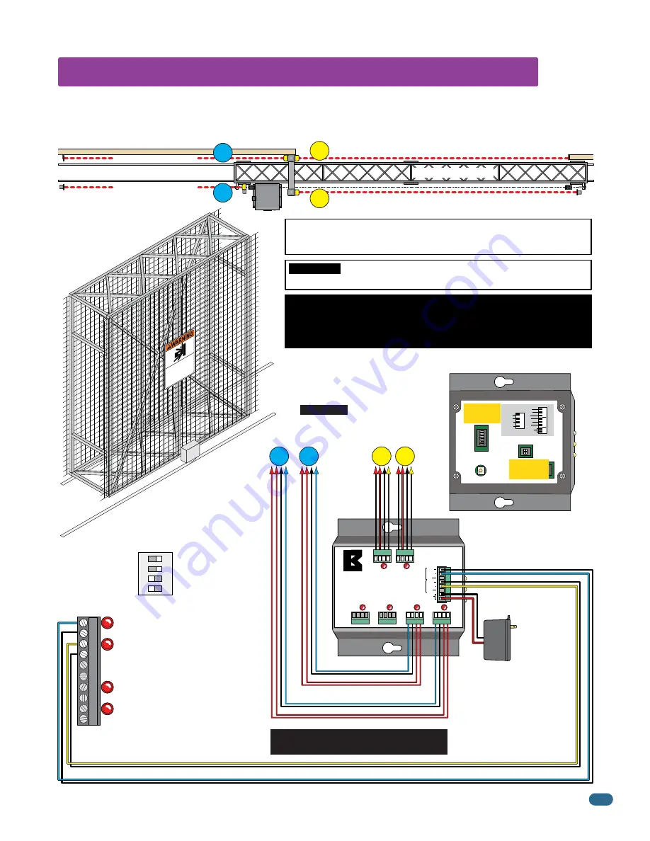
A wide gate will not be protected from obstructions using only one photocell in each cycling direction. DoorKing suggests using photocells on
BOTH
sides of a wide gate in the opening
AND
closing direction to better protect against obstructions during gate cycling. A MIM-62 (sold
separately) is needed to wire this type of setup (see below). Reversing edges should also be used to further protect against any entrapment
areas or potential obstructions of gate when necessary (not shown here).
DoorKing
suggests installing
UL 325 compliant wire
mesh (see page 2) on
BOTH
sides of a
WIDE
gate to prevent
access to hazards that might occur
inside of the gate frame.
Type of wiring to be used on ALL external devices:
A)
Type
CL2
,
CL2P
,
CL2R
, or
CL2X
.
B)
Other cable with
equivalent
or
better
electrical, mechanical, and flammability ratings.
IMPORTANT:
Monitored Photo and Edge sensors must be end-of-line resistive
types. See specific manufacturer's wiring manual for more information.
Entrapment Protection must be provided for the gate system where the risk
of entrapment or obstruction exists. The operator will NOT run without ONE
or more monitored type B1 or B2 external entrapment protection devices in
EACH direction of gate travel (minimum of 2 external devices required).
Moving Gate Can Cause
Serious Injury or Death
KEE
P CLEA
R!
Gat
e may
move at any
time
wi
tho
ut pr
ior war
ning.
Do no
t le
t ch
ildr
en op
era
te the gate or pl
ay
in
the gate a
rea
.
Th
is ent
rance
is for veh
icles on
ly.
Pe
destrians
must u
se se
par
ate entran
ce
.
4.4 Wide Gate Photocell Device Locations Sample

