9150-065-Y-12-20
31
FULL OPEN
D
4
NC
NO
1
2
3
4
5
6
7
8
9
10
1
ENABL
SHORT
2
3
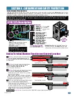
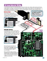
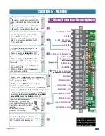
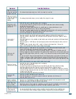
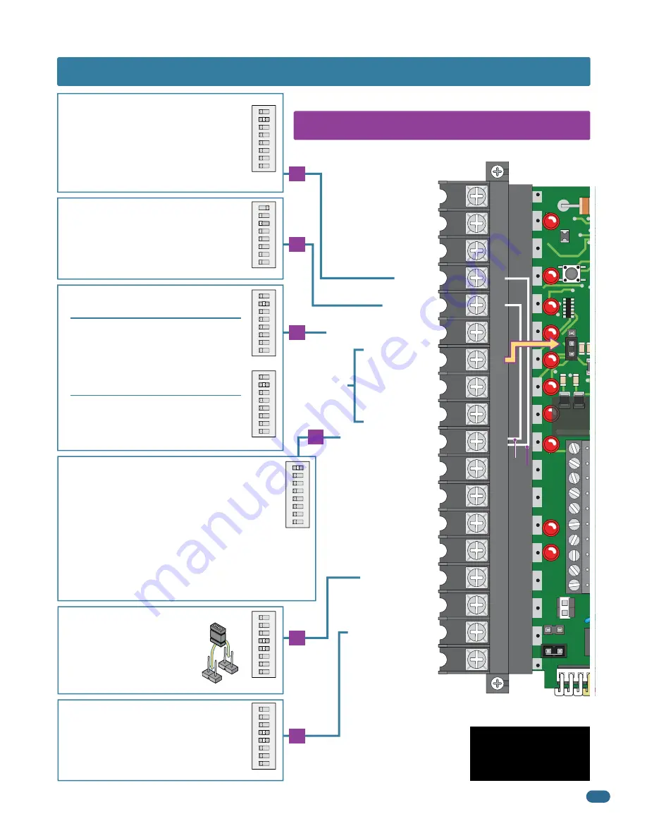
5.1 Main Terminal Description
15
10
6
5
Low Voltage Common
LED Indicator Output
Dry Relay Contact
Gate Tracker - Data
Gate Tracker - Busy
Entrapment Alarm
Alarm Reset
Exit Loop Logic Output
(DoorKing Loop Detectors ONLY)
Dry Relay Contact
Full Open
Partial Open
Standard Reverse or Stop
Low Voltage Common
Full Open
18
17
16
15
14
13
12
11
10
9
8
7
6
5
4
3
2
1
•
When gate is closed, this input will fully open
gate.
•
When gate is open and auto close timer SW 1,
switch 2 is turned ON, input will re-set and hold
timer.
•
When gate is open and auto close timer SW 1,
switch 2 is turned OFF, input will close gate.
•
When gate is closing, input will reverse gate.
ON
1
2
345678
SW 1
17
Provides 24 VDC, 250 ma. maximum to power
LED. Operation of LED is dependent on setting of
SW 1, switches 4 and 5 (See page 21).
ON
12
3
45
678
SW 1
Operation of relay is dependent on
setting of SW 1, switches 4 and 5.
Relay contacts can be set for Normally
Open (NO) or Normally Closed (NC)
operation.
Contact rating is 1 amp
maximum at 24-volts DC.
ON
12
3
45
678
SW 1
NO
NC
4
•
This input ONLY fuctions when gate is
fully
opened
or in the
closing cycle
.
•
When gate is open:
auto close timer
SW 1,
switch 2 is turned
ON
, input will re-set and hold
timer.
•
When gate is open:
auto close timer
SW 1,
switch 2 is turned
OFF
, input will prevent gate
from closing.
•
When gate is closing: input will
stop
gate when
SW 2, switch 2 is
ON
.
•
When gate is closing: input will
reverse
gate
when SW 2, switch 2 is
OFF
.
ON
1
2
345678
SW 2
ON
1
2
345678
SW 1
Jumper Wire SW 2, switch 2 OFF (Dual Operators only)
Jumper Wire SW 2, switch 2 OFF (Exit Loop Partial Open)
For long gate application. SW 2, switch 3
must be
OFF.
Same operation as #4
terminal above but will only open a closed
gate 14-Ft. or reverse a closing gate to the
14-Ft. open position.
ON
12
3
45678
SW 2
ON
1
2
345678
SW 2
-
Terminal #10 connected to terminal #5 will
PARTIALLY
open
plug-in exit loop detector (Single channel) for a single operator.
-
Terminal #10 connected to terminal #4 will
FULLY
open
bi-parting gates.
Dual operators ONLY using DoorKing’s
plug-in DUAL channel loop detector.
(Page 34).
•
lf SW 2, switch 1 is
ON
, the plug-in exit loop detector
(Single channel) will
FULLY
open the gate (Normal Setting).
Single operator use ONLY
.
•
lf SW 2, switch 1 is
OFF
, the normal exit loop port
function is used by terminal #10:
SECTION 5 - WIRING
UL 325
Terminal
Pages
25-29
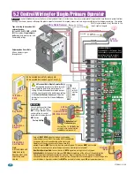
24 VAC - 250 mA max.
(See note below)
Terminal #3 Note:
Exceeding 250 mA of power from
this terminal may cause the circuit
board transformer to overheat,
causing intermittent problems.
3-Button Close
3-Button Open
(See page 32)
FIRE
3-Button Stop
(Pins 1 & 2 to Enable
NC-Stop Circuit)


