9150-065-Y-12-20
32
ON
EXI
LOO
FULL OPEN
DOORKING
4602-018
NC
NO
1
2
3
4
5
6
7
8
9
10
1
ENABLE STOP
SHORT PINS 1&2
2
3
18
17
16
15
14
13
12
11
10
9
8
7
6
5
4
3
2
1
FIRE
W
ARNING
MO
VI
NG
GA
TE
CAN
CA
USE
Ope
rate
ga
te onl
y wh
en
gate
are
a is
in s
ight
and
free
of pe
opl
e a
nd ob
struc
tions
.
Do
not
allow
chi
ldre
n to
play
in
gat
e a
rea
or
ope
rate
ga
te.
Do
not
sta
nd i
n gate
pa
th or
wa
lk th
rough
pa
th
w
hile
ga
te is
m
ovin
g.
Rea
d owne
r’s ma
nua
l an
d s
afe
ty ins
tru
ctio
ns
.
SER
IO
US
IN
JU
RY
OR
DEA
TH
CLASS
CER
TIF
IED
TO
CA
N/C
SA
C2
2.
2 N
O. 2
47
CO
NF
OR
MS
TO
AN
SI
/U
L-3
25
VEHI
CUL
AR
GA
TE O
PE
RA
TOR
HP
533
82
MO
DE
L
SE
RIAL
VO
LTS
PH
ASE
AMPS
60
Hz
MA
X
GA
TE
LO
AD
Door
Ki
ng
, Inc
., Ing
lew
ood,
CA
ON
ON
REVERS
E
SEN
SITIVIT
Y
REV
ER
SE
LOOP
EX
IT
LOOP
KE
Y SWITC
H
DOOR
KIN
G
4602
-0
10
SW
1
SW
2
OP
EN
TIM
ER
NC
1
2
3
4
5
NO
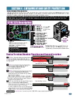
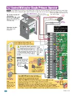
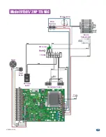
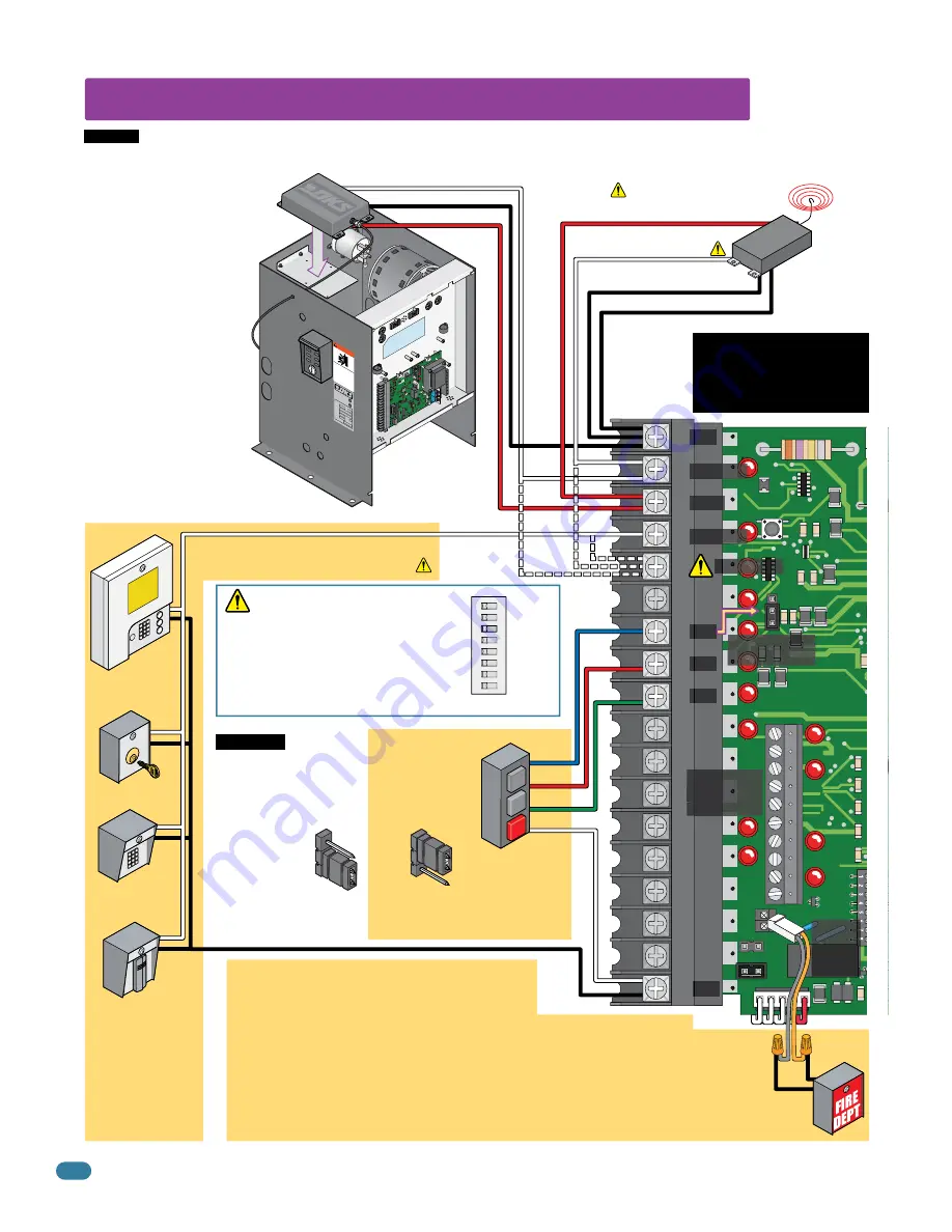
5.2 Control Wiring for Single/Primary Operator
Key Switch
Stand-Alone
Keypad
Stand-Alone
Card Reader
Telephone
Entry
Note:
All stand-alone and
telephone entry
devices must use a
separate power
source.
Gate will
ONLY OPEN
when this device is activated by
authorized personnel ONLY (fire, police, EMS) and operator
has power. Alarm will sound during entire open cycle.
Operator will then go into a hard shutdown once fully
opened. Operator
MUST
be reset to function normally again. This device
MUST
be mounted
in the line-of-site of gate so authorized personnel can monitor gate movement.
Dual Gate Operators Note:
Connect device to
BOTH
operators, both gates will fully open.
Com
Com
Relay -
#2 - Full Open.
#5 - Opens 14-feet.
Relay N.O. - #2 - Full Open.
#5 - Opens gate 14-feet.
250 mA
max.
3-Wire Radio Receiver
ON
12
3
45678
SW 2
SW 2,
switch 3
must be
OFF
.
Relay Com
24 Volt Com
24 Volt - 250 mA max.
4-Wire
Receiver
#5 Terminal Note (Single Operator Only):
Any opening device connected to terminal
#5 will open the gate to the partial open 14-ft
setting. External entrapment protection devices
will also open the gate to the partial open setting.
If the
Inherent Reverse Sensor
gets activated
during the close cycle, it will always
fully
open
the gate.
24 volt
Full Open
Full Open
Stop
Com
Power
Com
Open
Close
Partial Open
3-Button Control
Station Jumper
Important:
Controls intended for user activation must be located at least six (6) feet away from any moving part of the gate and where the user is prevented from
reaching over, under, around or through the gate to operate the controls. Emergency access controls only accessible by authorized personnel (e.g., fire, police,
EMS) may be placed at any location in the
line-of-sight of the gate.
3
4
5
2
UL 325
Terminal
Pages 25-29
Open
Jumper Pins 1 & 2
ONLY
when
using a 4-wire control station
to
enable
stop terminal #7.
3-Button Control
Station Jumper
Factory Setting
Stop
Close
Com
4-Wire
3-Button
Control Station
(NC-Stop Circuit)
#4-Connected device fully opens gate.
#5-Connected device opens gate 14-feet.
Terminal #3 Note:
Exceeding 250 mA of power from
this terminal may cause the circuit
board transformer to overheat,
causing intermittent problems.
OPE
N
STOP
CLOSE
1
2
3
1
2
3
IMPORTANT:
Leave 3-button control station
jumper pins on 2 & 3 when
NOT
wiring a
4-wire
3-button
control station to control
board otherwise operator will
NOT
fuction.
Type of wiring to be used on ALL
external devices:
A)
Type
CL2
,
CL2P
,
CL2R
, or
CL2X
.
B)
Other cable with
equivalent
or
better
electrical, mechanical, and
flammability ratings.
Activation Note:
Activation of this device will
OPEN
gate regardless of the status of the open direction
monitored external entrapment protection device(s). If gate is opening, and the operator’s
inherent
entrapment protection system detects an obstruction, the operator will reverse approx. 2 inches and go into
a hard shutdown. Operator reset button
MUST
be pushed to function again
OR
cycle operator’s power.
2-Pin
Supplied
Wire
Harness
Fire Dept
Open
Polypropylene Cover Note:
Allows wireless signal
through cover.

