16
OPERATING INSTRUCTIONS
7/124 - 10/104, 10/124 - 14/114, 14/84
PRIOR TO STARTING
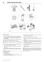
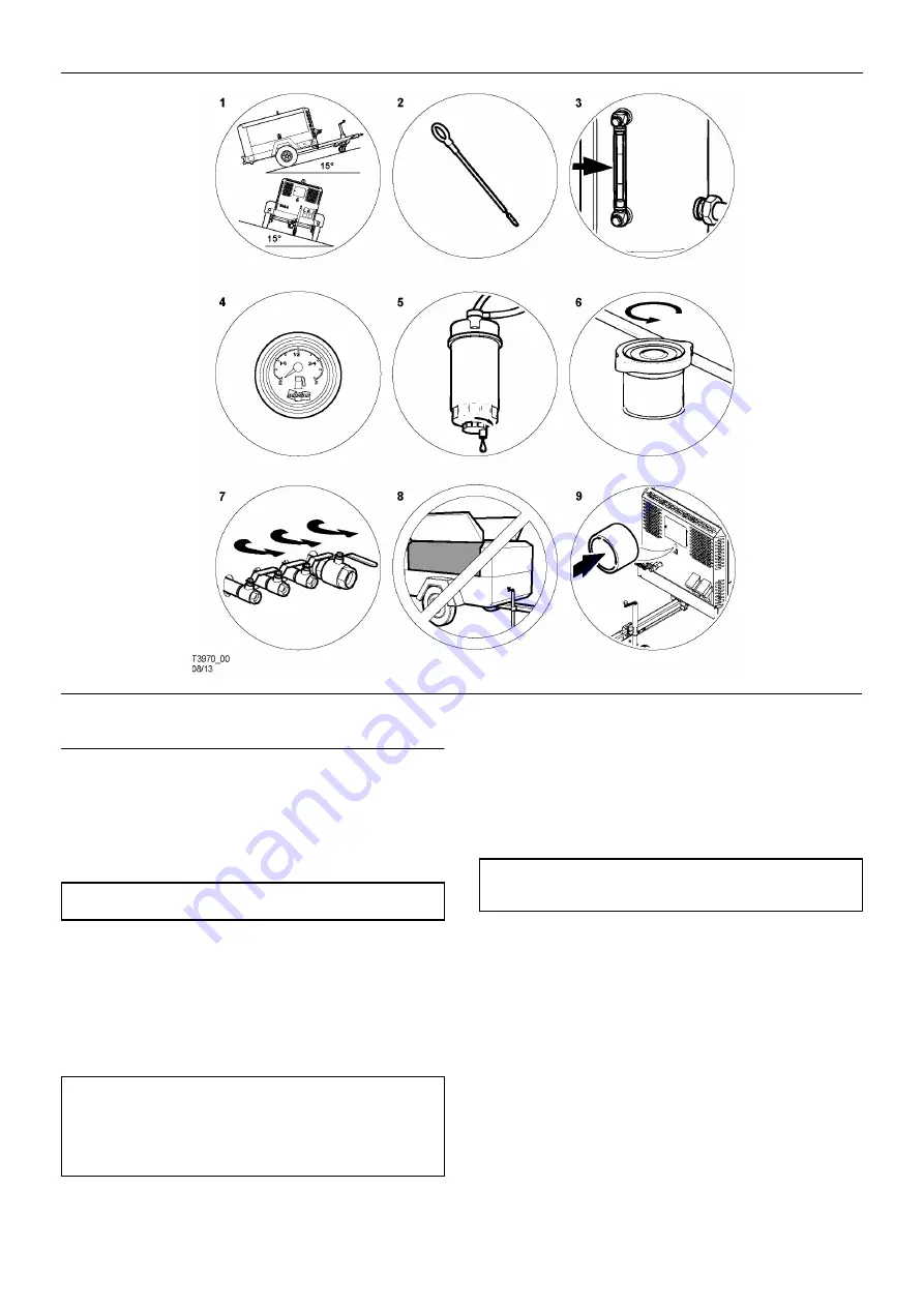
1. Place the unit in a position that is as level as possible. The design
of the unit permits a 15 degree lengthways and sideways limit on
out of level operation. It is the engine, not the compressor, that is
the limiting factor.
When the unit has to be operated out of level, it is important to keep the
engine oil level near the high level mark (with the unit level).
2. Check the engine lubrication oil in accordance with the operating
instructions in the
Engine Operator’s Manual.
3. Check the compressor oil level in the sight glass located on the
separator tank.
4. Check the diesel fuel level. A good rule is to top up at the end of
each working day. This prevents condensation from occurring in the
tank.
5. Drain the fuel filter water separator of water, ensuring that any
released fuel is safely contained.
6. Check the radiator coolant level (with the unit level).
7. Open the service valve(s) to ensure that all pressure is relieved
from the system. Close the service valve(s) when all pressure is
relieved.
9. Check that the emergency stop switch is not engaged. Pull knob to
release if necessary.
10.Close the manual relief valve inside the unit, on the top of the
separator tank.
When starting or operating the machine in temperatures below or
approaching 0°C (32°F), ensure that the operation of the regulation
system, the unloader valve, the safety valve, and the engine are not
impaired by ice or snow, and that all inlet and outlet pipes and ducts
are clear of ice and snow.
CAUTION:
Do not overfill either the engine or the compressor with
oil.
CAUTION:
When refuelling:-
•
switch off the engine.
•
do not smoke.
•
extinguish all naked lights.
•
do not allow the fuel to come into contact with hot surfaces.
•
wear personal protective equipment.
8.
CAUTION:
Do not operate the machine with the canopy/doors in
the open position as this may cause overheating and operators to
be exposed to high noise levels.
Summary of Contents for 10/104
Page 2: ......
Page 4: ......
Page 11: ...ISO SYMBOLS 7 7 124 10 104 10 124 14 114 14 84 Replace any cracked protective shield ...
Page 83: ...MAINTENANCE 79 7 124 10 104 10 124 14 114 14 84 ...
Page 84: ...80 MAINTENANCE 7 124 10 104 10 124 14 114 14 84 ...
Page 92: ...88 MACHINE SYSTEMS 7 124 10 104 10 124 14 114 14 84 ...
Page 108: ......
Page 109: ......


