OPERATING INSTRUCTIONS
53
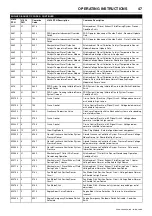
7/124 - 10/104, 10/124 - 14/114, 14/84
Deactivate Custom pressure function, pressure rises to 10 bar
(nominal pressure) and engine speed remains the same.
Set Custom pressure below LO mode pressure, e.g. 6 bar and activate
function.
Machine operates in HI mode, pressure drops from 10 to 6 bar and
engine speed remains the same.
Machine operates in LO mode, pressure remains at 6 bar and engine
speed rises to 2200 rpm.
Switch to HI mode, pressure remains at 6 bar and engine speed drops
to 1950 rpm.
Deactivate Custom pressure function, pressure rises to 10 bar
(nominal pressure) and engine speed remains the same.
BUNDED BASE
Description
This machine is fitted with bund equipment to contain leakages and
spillages, which occur within the machine enclosure.
The bund will contain all fluids normally installed in the machine, plus
an additional 10%.
Drains for engine water & oil and compressor oil are located at the front
corner of the machine The rear air intake is covered to prevent
rainwater ingress. Ensure that the cover is not prevented from moving.
Draining of contaminated fluids
Contaminated fluid must be removed by authorized personnel only.
Captured fluids can be drained from the bund by uncoupling the flexible
pipe secured at the rear / side. This pipe must be re-secured after
draining.
Drainage of machine fluids
During maintenance operations drain machine fluids using the drain
ports indicated.
When cleaning of the fuel tank is needed, tank should be removed from
compressor.
Captured fluids can be drained from the bund by uncoupling the flexible
pipe secured at the rear / side. This pipe must be re-secured after
draining.
AFTERTREATMENT DEVICES
The Aftertreatment Architecture for the QSB6.7 T4F engine used in this
compressor is based on three key subsystems:
1. Diesel Oxidation Catalyst (DOC)
2. Selective Catalytic Reduction (SCR)
3. Diesel Exhaust Fluid (DEF) Dosing System
Diesel Oxidation Catalyst (DOC)
Modern catalytic converters consist of a monolith honeycomb
substrate coated with platinum group metal catalyst, packaged in a
stainless steel container. The honeycomb structure with many small
parallel channels presents a high catalytic contact area to exhaust
gasses. As the hot gases contact the catalyst, several exhaust
pollutants are converted into harmless substances: carbon dioxide and
water.
The diesel oxidation catalyst is designed to oxidize carbon monoxide,
gas phase hydrocarbons, and the SOF fraction of diesel particulate
matter to CO
2
and H
2
O.
Selective Catalytic Reduction (SCR)
The purpose of the SCR system is to reduce levels of NOx (oxides of
nitrogen emitted from engines) that are harmful to our health and the
environment. SCR is the aftertreatment technology that treats exhaust
gas downstream of the engine. Small quantities of diesel exhaust fluid
(DEF) are injected into the exhaust upstream of a catalyst, where it
vaporizes and decomposes to form ammonia and carbon dioxide. The
ammonia (NH
3
) is the desired product which in conjunction to the SCR
catalyst, converts the NOx to harmless nitrogen (N
2
) and water (H
2
O).
Diesel Exhaust Fluid (DEF)
DEF is the reactant necessary for the functionality of the SCR system.
It is a carefully blended aqueous urea solution of 32.5% high purity
urea and 67.5% deionized water.
A 32.5% solution of DEF will begin to crystallize and freeze at 12 deg
F (-11 deg C). At 32.5%, both the urea and water will freeze at the
same rate, ensuring that as it thaws, the fluid does not become diluted,
or over concentrated. The freezing and thawing of DEF will not cause
degradation of the product.
During cold weather engine operation the engine coolant will be used
to heat up and thaw the DEF fluid, there is a delay built in to the engine
software to ensure engine operation even with frozen DEF fluid during
warmup.
OPERATION OF THE AFTERTREATMENT DEVICES
Diesel Aftertreatment Device specific lights
1. HEST Lamp
High Exhaust System Temperature
•
Lights when the engine is in an active cleaning phase.
•
Higher-than-normal exhaust temperatures may exist due to active
aftertreatment system cleaning.
•
Operator should make sure the exhaust pipe outlet is not directed
at any surface or material that may become hazardous.
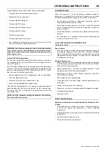
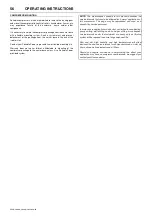
WARNING: Major leakages or spillages must be drained before
machine is towed.
Summary of Contents for 10/104
Page 2: ......
Page 4: ......
Page 11: ...ISO SYMBOLS 7 7 124 10 104 10 124 14 114 14 84 Replace any cracked protective shield ...
Page 83: ...MAINTENANCE 79 7 124 10 104 10 124 14 114 14 84 ...
Page 84: ...80 MAINTENANCE 7 124 10 104 10 124 14 114 14 84 ...
Page 92: ...88 MACHINE SYSTEMS 7 124 10 104 10 124 14 114 14 84 ...
Page 108: ......
Page 109: ......

