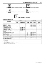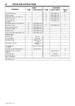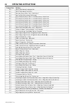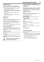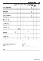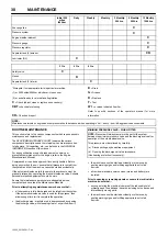
MAINTENANCE
30
12/150_23136591
−
C en
Initial 500
miles
/850 km
Daily
Weekly
Monthly
3 Monthly.
250 hrs.
6 Monthly.
500 hrs
12 Monthly.
1000 hrs
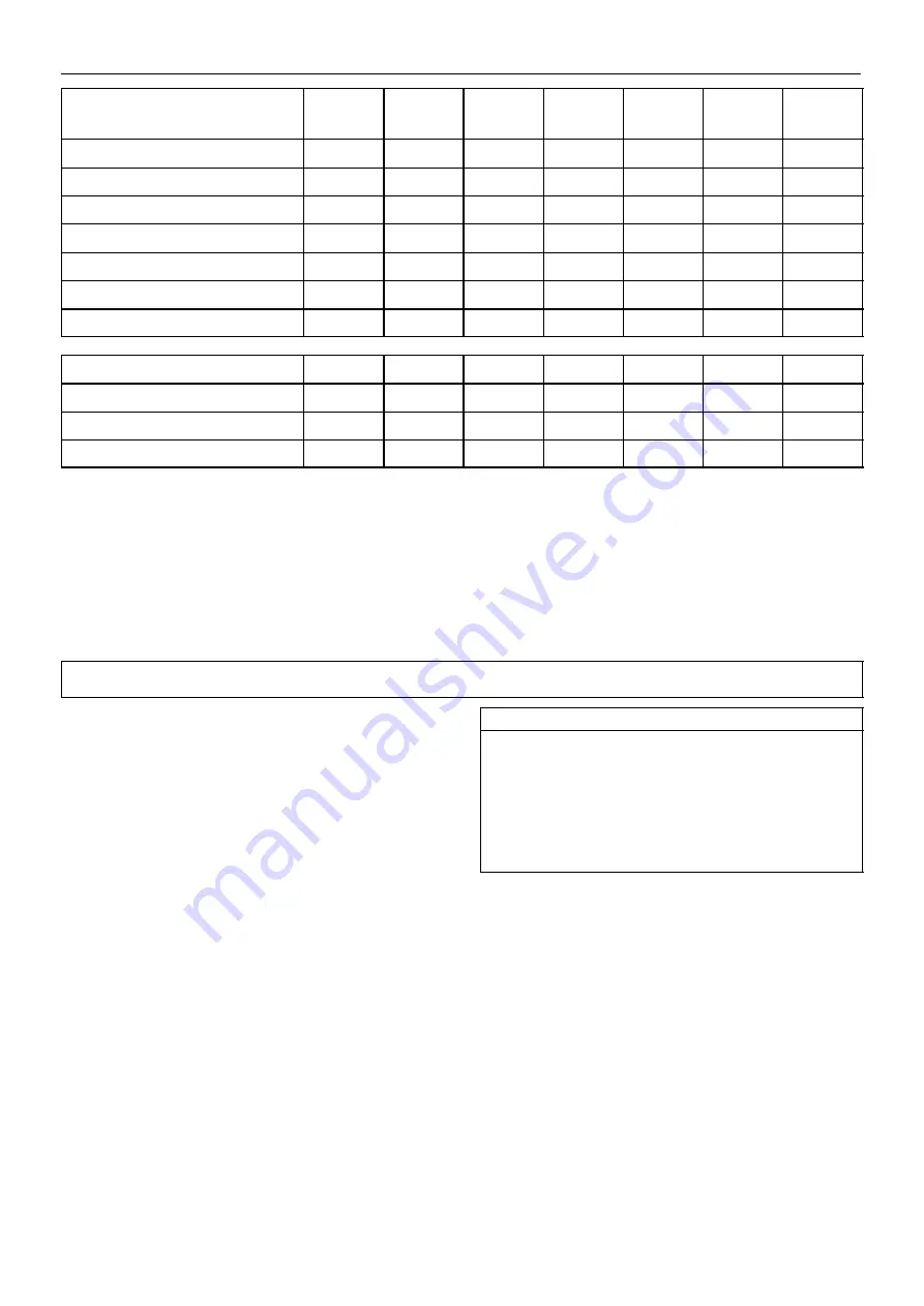
Scavenge line
C
Pressure system
C
Engine breather element
C
Pressure gauge
C
Pressure regulator
C
Separator tank (2) exterior
CR
Lubricator (Fill)
C
2 Yrs
4 Yrs
6 Yrs
Safety valve
C
Hoses
R
Separator tank (2) interior
C
*Disregard if not appropriate for this particular machine.
(1)
or 3000 miles/5000km whichever is the sooner
(2)
or as defined by local or national legislation
C
=
Check (adjust, clean or replace as necessary)
CBT
=check before towing.
CR
=
Check and report
D
=
Drain
G
=
Grease
R
= Replace
T
=
Test
W I
= or when indicated if earlier.
Refer to specific sections of the operator’s manual for more
information.
NOTE:
Maintenance intervals on engine and compressor should be reduced when operating in “hot
−
dusty
−
humid & aggressive environments.
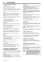
ROUTINE MAINTENANCE
This section refers to the various components which require periodic
maintenance and replacement.
The
SERVICE/MAINTENANCE CHART
indicates the various
components’ descriptions and the intervals when maintenance has
to take place. Oil capacities, etc., can be found in the
GENERAL
INFORMATION
section of this manual.
For any specification or specific requirement on service or
preventative maintenance for the engine, refer to the
Engine
Manufacturer’s Manual
.
Compressed air can be dangerous if incorrectly handled. Before
doing any work on the unit, ensure that all pressure is vented from
the system and that the machine cannot be started accidentally.
If the automatic blowdown fails to operate, then pressure must be
gradually relieved by operating the manual blowdown valve. Suitable
personal protective equipment should be worn.
Ensure that maintenance personnel are adequately trained,
competent and have read the Maintenance Manuals.
Prior to attempting any maintenance work, ensure that:
−
all air pressure is fully discharged and isolated from the system.
If the automatic blowdown valve is used for this purpose, then
allow enough time for it to complete the operation.
S
the discharge pipe / manifold area is depressurised by opening
the discharge valve, whilst keeping clear of any airflow from it.
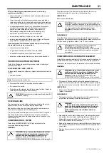
MINIMUM PRESSURE VALVE
−
WHEN FITTED
NOTE:
Pressure will always remain in the part of the system
between the minimum pressure valve and the discharge valve after
operation of the auto blowdown valve.
This pressure must be relieved by carefully:
(a) Disconnecting any downstream equipment.
(b) Opening the discharge valve to atmosphere.
(Use hearing protection if necessary).
the machine cannot be started accidently or otherwise, by
posting warning signs and/or fitting appropriate anti
−
start
devices.
all residual electrical power sources (mains and battery) are
isolated.
Prior to opening or removing panels or covers to work
inside
a
machine, ensure that:
−
anyone entering the machine is aware of the reduced level of
protection and the additional hazards, including hot surfaces and
intermittently moving parts.
the machine cannot be started accidently or otherwise, by
posting warning signs and/or fitting appropriate anti
−
start
devices.

