background image

46

MAINTENANCE

9/275, 9/305, 12/250, 17/240, 21/220

COMPRESSOR LUBRICATION

Portable Compressor Fluid Chart

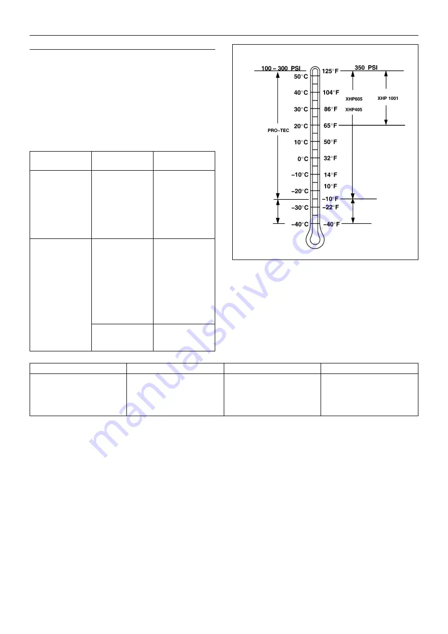
Refer to these charts for correct compressor fluid required. Note

that the selection of fluid is dependent on the design operating
pressure of the machine and the ambient temperature expected to be
encountered before the next oil change.

Note: Fluids listed as “preferred” are required for extended
warranty.

Compressor oil carryover (oil consumption) may be greater

with the use of alternative fluids.

Preferred Doosan Fluids - Use of these fluids with original Doosan

branded filters can extend airend warranty. Refer to operator’s manual
warranty section for details or contact your Portable Power
representative.

Design Operating 
Pressure

Ambient 
Temperature

Specification

100 psi to 300 psi

-23

°

C to 52

°

C

(-10

°

F to 125

°

F)

Preferred:

PRO-TEC

Alternate:
ISO Viscosity Grade 
46 with rust and 
oxidisation inhibitors, 
designed for air 
compressor service.

350 psi

-23

°

C to 52

°

C

(-10

°

F to 125

°

F)

Preferred:

XHP 605

Alternate:

XHP 405

ISO Viscosity Grade 
68 Group 3 or 5 with 
rust and oxidisation 
inhibitors, designed 
for air compressor 
service.

18

°

C to 52

°

C

(65

°

F to 125

°

F) 

Preferred:

XHP 605
XHP 1001

RATED OPERATING PRESSURE

consult factory

consult

factory

 Doosan Preferred Fluids

19.0 Litre

208.2 Litre

836 Litre

PRO-TEC

89292973

89292981

22082598

XHP 605

22252076

22252050

22252068

XHP 1001

35612738

35300516

-

XHP 405

22252126

22252100

22252118

Summary of Contents for 12/250

Page 1: ...n and must be made available to personnel who operate and maintain this machine 46562208_en_A_05 12 9 275 9 305 12 250 17 240 21 220 OPERATION MAINTENANCE MANUAL Original Instruction 9 275 9 305 SERIAL No 895000 12 250 17 240 SERIAL No 883000 21 220 ...

Page 2: ...that the machine display the CE Mark and conform to various directives In such cases the design specification of this machine has been certified as complying with EC directives Any modification to any part is absolutely prohibited and would result in the CE Certification and marking being rendered invalid A declaration of that conformity follows SAMPLE ...

Page 3: ......

Page 4: ......

Page 5: ...on 47 MACHINE SYSTEMS Electrical system Piping instrumentation system 53 FAULT FINDING 55 OPTIONS 62 ENGINE INSTRUCTION MANUAL 93 PARTS ORDERING ABBREVIATIONS SYMBOLS Contact the company for serial number Up to Serial No From Serial No Not illustrated Option WDG Generator option AR As required HA High ambient machine S R G Site running gear H R G High speed running gear bg Bulgarian cs Czech da Da...

Page 6: ...in the approved parts list may create hazardous conditions over which the company has no control Therefore the company cannot be held responsible for equipment in which non approved repair parts are installed The company reserves the right to make changes and improvements to products without notice and without incurring any obligation to make such changes or add such improvements to products sold ...

Page 7: ...sure control WARNING Corrosion risk WARNING Air gas flow or Air discharge WARNING Pressurised vessel WARNING Hot and harmful exhaust gas WARNING Flammable liquid WARNING Maintain correct tyre pressure Refer to the GENERAL INFORMATION section of this manual WARNING Before connecting the tow bar or commencing to tow consult the Operation Maintenance manual WARNING For operating temperature below 0 C...

Page 8: ...is machine Do not remove the Operating and Maintenance manual and manual holder from this machine Do not stack Do not operate the machine without the guard being fitted Do not stand on any service valve or other parts of the pressure system Do not operate with the doors or enclosure open Do not use fork lift truck from this side Do not exceed the trailer speed limit No naked lights Do not open the...

Page 9: ...taken When parking use prop stand handbrake and wheel chocks Compressor oil filling Diesel fuel No open flame Parking brake Rough Service Designation Wet Location Operation Replace any cracked protective shield Oil drain Operational status of the engine emission filter Engine emissions system temperature may be high Disable active regeneration of the engine emission filter ...

Page 10: ...spected be free from defects and be replaced according to the Manual instructions Avoid bodily contact with compressed air The safety valve located in the separator tank must be checked periodically for correct operation Materials The following substances may be produced during the operation of this machine brake lining dust engine exhaust fumes AVOID INHALATION Ensure that adequate ventilation of...

Page 11: ... 1500 362 25 2500 362 25 2500 Maximum pressure ratio absolute 8 1 8 1 8 1 18 9 1 18 9 1 Operating ambient temperature range C F 10 to 46 14 to 115 10 to 46 14 to 115 10 to 46 14 to 115 10 to 46 14 to 115 10 to 46 14 to 115 Maximum discharge temperature C F 120 248 120 248 120 248 120 248 120 248 COMPRESSOR Cooling system Oil Injection Oil capacity Litre 75 75 75 75 75 Maximum oil system temperatur...

Page 12: ...Litre 58 58 58 58 58 Max gross weight kg 5160 5160 5160 5360 5360 Shipping weight kg 4760 4760 4760 4960 4960 INFORMATION ON AIRBORNE NOISE CE regions The A weighted emission sound pressure level 83 dB A uncertainty 1 dB A The A weighted emission sound power level 100 dB A uncertainty 1 dB A The operating conditions of the machinery are in compliance with ISO 3744 1995 and EN ISO 2151 2004 WEIGHT ...

Page 13: ...ion of the machine ensure that there is sufficient clearance for ventilation and exhaust requirements observing any specified minimum dimensions to walls floors etc Adequate clearance needs to be allowed around and above the machine to permit safe access for specified maintenance tasks Ensure that the machine is positioned securely and on a stable foundation Any risk of movement should be removed ...

Page 14: ... any released fuel is safely contained 6 Check the radiator coolant level with the unit level 7 Open the service valve s to ensure that all pressure is relieved from the system Close the service valve s 9 Check the emergency stop Pull knob to release 10 Close the manual relief valve inside the unit on the top of the separator tank When starting or operating the machine in temperatures below or app...

Page 15: ...ompressor control system and ViewPort 3C RUN Turns on engine control system 3D START Initiates engine cranking Momentary position 4 Service Air Switch Momentary contact switch Allows engine to warm up at low compressor pressure 5 Discharge Air Pressure Gauge Indicates pressure in receiver tank normally from 0 psi kPa to the rated pressure of the machine 6 Engine Tachometer Indicates engine speed i...

Page 16: ...sing the Right or Left functions of the Navigation Button and selecting screen in Menu Bar Initial Screen The initial screen of the ViewPort displays digital gauges indicating current values of key operating parameters Pressing the centre of the Navigation Button ENTER activates the screen Use the Up or Down functions to scroll the small gauges to view all available gauges The gauges displayed wil...

Page 17: ...yellow Continue to set all options using the same sequence of steps Press the Down function until no options are highlighted Press the Right function to select the gauges screen on the Menu Bar Press the centre of the Navigation Button ENTER to save settings Restart ViewPort to save all options Info Screen The Info Screen accesses information resources including Parts Manual Operation and Maintena...

Page 18: ...Up or Down functions Use Left function of Navigation Button to back out of currently selected resource At main menu of info screen another resource may be selected Continue to use the Left function to exit the Info Screen Use the Up or Down function of the Navigation Button to highlight the CAN Devices screen Press the centre of the Navigation Button ENTER to activate the CAN Devices screen Curren...

Page 19: ...e Events Screen will appear automatically upon the occurrence of any Engine or Equipment Fault Code and will display all current Events in an automatically cycling loop The number of current Faultcode Events will be displayed in the Status Bar at the top of the ViewPort screen ...

Page 20: ...rature Airend discharge temperature greater than or equal to 248 F 30 120 C 248 F 3 Low Airend Oil Pressure Airend oil pressure below 10 psi 31 0 7 bar 10 PSI 3 Airend Discharge Temperature Sensor Airend discharge temperature sensor reading out of range 32 10 Separator Tank Pressure Sensor Separator tank pressure sensor reading out of range 33 0 5V 4 5V High Separator Tank Pressure At Start Separa...

Page 21: ...nsor Regulation system pressure sensor reading out of range 54 0 5V 4 5V Emergency Stop Activated Emergency Stop button has been activated 55 3 Low Start Pressure Separator tank pressure below 50 psi 20 seconds after start 56 3 5 bar 50 PSI Ambient Temperature Sensor Ambient temperature sensor reading out of range 58 OTBV Solenoid Malfunction Oil temperature bypass valve solenoid current out of ra...

Page 22: ...ccelerator Pedal or Lever Sensor System Error Received Network Data In Error 93 2 528 Engine Net Brake Torque Data Erratic Intermittent or Incorrect Auxiliary Constrained Operation Curve Validation Switch Data Erratic Intermittent or Incorrect 95 16 2372 Fuel Pressure Data Valid but Above Normal Operating Range Moderately Severe Level Fuel Filter Differential Pressure Data Valid But Above Normal O...

Page 23: ... Severe Level Turbocharger 1 Speed Low Data Valid but Below Normal Operational Range Moderately Severe Level 105 0 155 Engine Intake Manifold 1 Temperature Data Valid but Above Normal Operational Range Most Severe Level Intake Manifold Air Temperature High Data Valid but Above Normal Operational Range Most Severe Level 105 3 153 Engine Intake Manifold 1 Temperature Voltage Above Normal or Shorted ...

Page 24: ... Valid but Above Normal Operational Range Most Severe Level Injector Metering Rail 1 Pressure Data Valid but Above Normal Operational Range Most Severe Level 157 1 2249 Engine Injector Metering Rail 1 Pressure Data Valid but Below Normal Operational Range Most Severe Level Injector Metering Rail 1 Pressure Data Valid but Below Normal Operational Range Most Severe Level 157 3 451 Engine Injector Me...

Page 25: ...ltage Below Normal or Shorted to Low Source Exhaust Gas Recirculation EGR Temperature Sensor Circuit Voltage Below Normal or Shorted to Low Source 412 15 2961 Engine Exhaust Gas Recirculation 1 Temperature Data Valid but Above Normal Operating Range Least Severe Level Exhaust Gas Recirculation EGR Temperature Data Valid but Above Normal Operating Range Least Severe Level 412 16 2962 Engine Exhaust...

Page 26: ...al Update Rate VGT Actuator Driver Circuit Abnormal Update Rate 641 12 2634 Engine Variable Geometry Turbocharger Actuator 1 Bad Intelligent Device or Component VGT Actuator Controller Bad intelligent Device or Component 641 13 2449 Engine Variable Geometry Turbocharger Actuator 1 Out of Calibration VGT Actuator Controller Out of Calibration 641 15 1962 Engine Variable Geometry Turbocharger Actuat...

Page 27: ...to High Source 974 4 134 Remote Accelerator Pedal Position Voltage Below Normal or Shorted to Low Source Remote Accelerator Pedal or Lever Position Sensor Circuit Voltage Below Normal or Shorted to Low Source 974 19 288 Remote Accelerator Pedal Position Received Network Data in Error SAE J1939 Multiplexing Remote Accelerator Pedal or Lever Data Error Received Network Data In Error 1073 3 2367 Engi...

Page 28: ...ressure Sensor Input 2 Circuit Voltage Above Normal or Shorted to High Source 1388 4 298 Auxiliary Pressure 2 Voltage Below Normal or Shorted to Low Source Auxiliary Pressure Sensor Input 2 Circuit Voltage Below Normal or Shorted to Low Source 1388 14 296 Auxiliary Pressure 2 Special Instructions Auxiliary Pressure Sensor Input 1 Special Instructions 1623 2 3213 Tachograph Output Shaft Speed Data ...

Page 29: ...reatment 1 Exhaust Gas Temperature 1 Voltage Below Normal or Shorted to Low Source Aftertreatment Exhaust Gas Temperature 1 Circuit Voltage Below Normal or Shorted to Low Source 3241 13 1663 Aftertreatment 1 Exhaust Gas Temperature 1 Out of Calibration Aftertreatment Exhaust Gas Temperature 1 Swapped Out of Calibration 3242 0 3311 Aftertreatment 1 Diesel Particulate Filter Intake Gas Temperature D...

Page 30: ...9 Aftertreatment 1 Diesel Particulate Filter Differential Pressure Voltage Above Normal or Shorted to High Source Aftertreatment Particulate Filter Differential Pressure Sensor Circuit Voltage Above Normal or Shorted to High Source 3251 4 1881 Aftertreatment 1 Diesel Particulate Filter Differential Pressure Voltage Below Normal or Shorted to Low Source Aftertreatment Particulate Filter Differentia...

Page 31: ...e Engine Air Shutoff Circuit Voltage below normal or shorted to low source 3703 31 2777 Diesel Particulate Filter Active Regeneration Inhibited Due to Inhibit Switch Not Available or Condition Exists Particulate Trap Active Regeneration Inhibited Due to Inhibit Switch Condition Exists 3936 15 1981 Aftertreatment Diesel Particulate Filter System Data Valid but Above Normal Operating Range Least Sev...

Page 32: ...uit Voltage Below Normal or Shorted to Low Source 520320 7 2699 Crankcase Depression Valve Mechanical System not Responding or Out of Adjustment Crankcase Depression Valve Mechanical System Not Responding or Out of Adjustment 520435 12 3222 Glow Plug Module Bad Intelligent Device or Component Glow Plug Module Bad intelligent device or component 520441 3 3136 Engine Exhaust Gas Recirculation EGR Ou...

Page 33: ...en return to idle speed after warming up 6 When ready for full pressure and after the compressor has warmed up press the service air button The engine may accelerate to full load speed until the rated operating pressure is reached 7 Open the service valve s to supply air from the compressor and begin normal operation Normal Operation The Operator may observe and monitor operating parameters using ...

Page 34: ...t temperatures may exist due to active DPF regeneration Operator should make sure the exhaust pipe outlet is not directed at any surface or material that may become hazardous 2 DFP Lamp High Exhaust System Temperature Lights when the DPF is approaching the need for regeneration Operator should check to make sure the Regeneration Control Switch is in Normal Position Operator can continue to use the...

Page 35: ...pendent activation Indicates an active regen in progress and higher than normal exhaust temperatures may occur for typically 15 minutes The HEST lamp will activate according to temperature level set by the OEM No operator intervention or action is required Equipment works as normal There maybe a slight increase in engine noise with a change to the sound of the turbocharger Surface temperature of t...

Page 36: ...r duty cycle initiated active regen to occur Continually removes PM soot from the Diesel Particulate Filter when exhaust temperature is above 220 C Removes any excessive build up of PM soot from the filter by raising the exhaust temperature above 500 C with late injection fuel Removes any excessive build up of PM soot from the filter by raising the exhaust temperature above 500 C with late injecti...

Page 37: ...n belts fan airend etc Block axles so tyres are off ground and do not support any weight Disconnect battery cables Drain fuel system SHORT TERM STORAGE Machines that stand idle for extended periods of time greater than 30 days Start and operate the machine every 30 days Operate long enough to allow the engine and compressor to reach operating temperature Open and close the service valve to exercis...

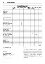
Page 38: ...Engine Oil Filter R Engine Oil R Engine Breather Filter R Engine Coolant Conditioner Filter R Engine Valve Lash C A Engine DPF Filter R WI C Check and act if required T Test D Drain R Replace CBT Check before towing R WI Replace or when indicated earlier C R Check and replace if required G C Grease and check C A Check and adjust if required Refer to specific sections of the operator s manual for m...

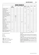
Page 39: ...own Valve C Engine Vibration Damper C R C Check and act if required T Test D Drain R Replace CBT Check before towing R WI Replace or when indicated earlier C R Check and replace if required G C Grease and check C A Check and adjust if required Refer to specific sections of the operator s manual for more information NOTE 500 and 1000 hour intervals are meant to be repeated at every 500 or 1000 hour...

Page 40: ... opening or removing panels or covers to work inside a machine ensure that anyone entering the machine is aware of the reduced level of protection and the additional hazards including hot surfaces and intermittently moving parts the machine cannot be started accidentally or otherwise by posting warning signs and or fitting appropriate anti start devices Prior to attempting any maintenance work on ...

Page 41: ...ter housing and remove the filter element by releasing the nut If the safety element is to be renewed thoroughly clean the interior of the filter housing prior to removing the safety element Inspection Check for cracks holes or any other damage to the element by holding it up to a light source or by passing a lamp inside Check the seal at the end of the element and replace if any sign of damage is...

Page 42: ... connector Final Fuel Filter Water Separator The final fuel filter 3 micron is mounted on the engine For maintenance details refer to the engine section of this manual FUEL FILTER WATER SEPARATOR The fuel filter water separator contains a filter element which should be replaced at regular intervals see the SERVICE MAINTENANCE CHART CHARGE COOLER PIPEWORK Inspect all hoses and clips on the charge c...

Page 43: ...ion Specification list ENGINE OIL FILTER ELEMENT The engine oil filter element should be changed at the engine manufacturer s recommended intervals Refer to the SERVICE MAINTENANCE CHART COMPRESSOR LUBRICATING OIL Refer to the SERVICE MAINTENANCE CHART in this section for service intervals Completely drain the receiver separator system including the piping and oil cooler by removing the drain plug...

Page 44: ...aring grease every 6 months Wheel bearings should be greased per the Maintenance Schedule in this manual The type of grease used should conform to specifications below Grease Thickener Type Lithium Complex Dropping Point 215 C 419 F Minimum Consistency NLGI No 2 Additives EP Corrosion Oxidation Inhibitors Viscosity Index 80 Minimum ...

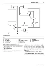
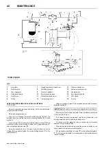
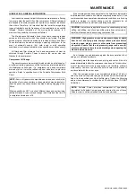
Page 45: ...e tachometer moves away from the full speed position before normal operating discharge pressure is attained then turn the adjusting knob A clockwise to increase the pressure Optimum adjustment is achieved when the throttle just moves from its full speed position and the pressure increases slightly Close the service valve The engine will slow to idle speed 9 275 9 305 12 250 A Adjusting knob E Orif...

Page 46: ...ine Note receiver pressure Warm up pressure should be 3 5 5 0 bar 50 70 p s i To increase the warm up pressure turn the air cylinder rod in an anti clockwise direction to open the butterfly valve To reduce warm up pressure turn air cylinder rod in clockwise direction to close butterfly valve When the engine is warmed up press the service air switch on the control panel to commence normal regulatio...

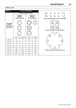
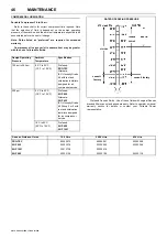
Page 47: ...TTERN TYPICAL CIRCULAR TORQUE PATTERN CAPSCREW OR NUT THREAD SIZE AND PITCH NOMINAL DESIGN TORQUE 8AE J249 GRADE 5 HEAD MARKING 8AE J249 GRADE 8 HEAD MARKING Nm FT LBF Nm FT LBF 1 4 20 11 8 16 12 5 16 18 24 17 33 25 3 8 16 42 31 59 44 7 16 14 67 49 95 70 1 2 13 102 75 144 106 9 16 12 148 109 208 154 5 8 11 203 150 287 212 3 4 10 361 266 509 376 ...

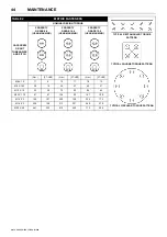
Page 48: ...T THREAD SIZE AND PITCH NOMINAL DESIGN TORQUE PROPERTY GRADE 8 8 HEAD MARKING PROPERTY GRADE 10 9 HEAD MARKING PROPERTY GRADE 12 9 HEAD MARKING Nm FT LBF Nm FT LBF Nm FT LBF M6 X 1 0 11 8 15 11 18 13 M8 X 1 25 26 19 36 27 43 31 M10 X 1 5 52 38 72 53 84 62 M12 X 1 75 91 67 126 93 147 109 M14 X 2 145 107 200 148 234 173 M16 X 2 226 166 313 231 365 270 M20 X 2 5 441 325 610 450 713 526 ...

Page 49: ...s in storage an earlier change may be necessary as oil deteriorates with time as well as by operating conditions An oil change is good insurance against the accumulation of dirt sludge or oxidized oil products Completely drain the separator tank piping and cooler If the oil is drained immediately after the compressor has been run for some time most of the sediment will be in suspension and therefo...

Page 50: ...fer to operator s manual warranty section for details or contact your Portable Power representative Design Operating Pressure Ambient Temperature Specification 100 psi to 300 psi 23 C to 52 C 10 F to 125 F Preferred PRO TEC Alternate ISO Viscosity Grade 46 with rust and oxidisation inhibitors designed for air compressor service 350 psi 23 C to 52 C 10 F to 125 F Preferred XHP 605 Alternate XHP 405...

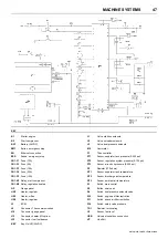
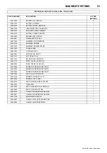
Page 51: ... low fuel beacon KEY Key On Off 24VDC L1 Valve start run solenoid L2 Valve unloader solenoid L3 Valve dual pressure solenoid M8 Hourmeter P1 Titan controller PT1 Sensor separator tank pressure 0 225 psi PT2 Sensor regulation system pressure 0 100 psi PT3 Sensor airend oil pressure 0 225 psi R1 Resistor 270 ohms RT1 Sensor separator tank temperature RT2 Sensor discharge air temperature RT3 Sensor a...

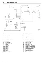
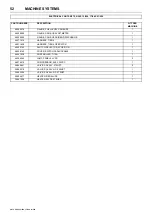
Page 52: ...F9 Fuse 10A FB1 F10 Fuse 15A FB1 K5 Relay switched power FG Earth frame G1 Alternator engine HR1 Heater engine intake air IQ IQ system option J3 ECM J5A Connector engine ECM service J7 Connector IQ option J8 Connector Autostart option J11 Sensor coolant level J14 Sensor DPF pressure J25 Sensor DPF temperature J30 Connector exterior work light option J31 Connector interior work light option J33 Con...

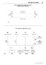
Page 53: ...ENGINE ECM J1939 CAN HI TITAN CONTROLLER J1939 CAN LO ENGINE ECM VIEWPORT J1939 CAN BUSS CONNECTION LAYOUT MAIN CONTROLLER KEYSWITCH SIGNAL TERMINATOR TERMINATOR ENGINE TACHOMETER ENGINE ECM TITAN COMMUNICATION CONNECTOR CUMMINS ECM SERVICE CONNECTOR OPTIONAL IQ ICU CONTROLLER OPTIONAL AUTOSTART CONTROLLER ...

Page 54: ...ALVES PRESSURE SWITCHES PRESSURE SENSORS EMERGENCY STOP FUSE RELAY CENTRE BATTERY STARTING AND CHARGING REGULATION HEATERS TEMPERATURE SENSORS ENGINE ECM ECM SERVICE CONNECTOR DPF SENSORS COOLANT LEVEL SENSOR WATER IN FUEL SENSOR ENGINE INTAKE AIR HEATER RELAY CONTROL PANEL HARNESS COMPRESSOR HARNESS ENGINE HARNESS BATTERY DISCONNECT SWITCH ENGINE INTAKE AIR HEATER FUSE ENGINE INTAKE AIR HEATER EN...

Page 55: ...2 FUSEHOLDER 1 46561563 FUSE AMG 150A 1 46562041 CONTACTOR 24VDC 1 89303127 E STOP BUTTON 1 89303135 EM STOP NC CONTACTS 2 54496773 PRES TRANS 0 225 PSIG 2 36920825 PRES TRANS 0 100 PSIG 1 23294820 SENSOR TEMPERATURE 3 8 NPT 1 23294820 SENSOR TEMPERATURE 3 8 NPT 1 23294820 SENSOR TEMPERATURE 3 8 NPT 1 36847838 SWITCH VAC 20 WATER 1 22769186 SENSOR COOLANT LVL 5V 1 46578039 SENSOR FUEL LEVEL 1 4656...

Page 56: ...806 GAUGE CAN BUSS AIREND DISCHARGE 1 46571519 HARNESS TIER 4 1 46571639 HARNESS TIER 4 OPERATOR 1 46556142 SWITCH SELECTOR 3 POSITION 1 46556145 COVER SWITCH PADLOCKABLE 1 46551938 CONTROLLER TITAN 1 46556345 LAMP PANEL 24 VDC 2 46576919 COMPRESSOR ELEC 24VDC 1 36840841 VALVE SOL 24V 375NPT 2 36842318 VALVE SOL 24V NO 250NPT 1 36842300 VALVE SOL 24V NC 375NPT 1 36854677 HEATER REG 24VDC 1 3684152...

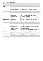
Page 57: ...not run or engine shuts down prematurely Electrical fault Test the electrical circuits Low engine oil pressure Check the oil level and oil filter s Safety shut down system in operation Check the safety shut down switches Fuel starvation Check the fuel level and fuel system components Replace the fuel filter if necessary Switch failure Test the switches High compressor oil temperature Check the com...

Page 58: ... Perforated separator element Replace the separator element Pressure in the system is too low Check the minimum pressure valve or sonic orifice Safety valve operates Operating pressure too high Check the setting and operation of the regulator valve piping Incorrect setting of the regulator Adjust the regulator Faulty regulator Replace the regulator Inlet valve set incorrectly Refer to SPEED AND PR...

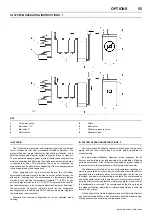
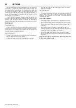
Page 59: ...ater system Standard Non Louvred configuration not to be operated below freezing IQ SYSTEM OPERATING INSTRUCTIONS 2 The compressed air exits the separator tank through the top cover piping and can then travel along one of two paths selectable via manual valving One path allows Standard Operation which bypasses the IQ System and delivers air quality equivalent to a standard oil flooded portable com...

Page 60: ...iction exceeds recommended values Weekly Maintenance Remove Y strainer screens at the bottom of the moisture separator and both filters and clean out any residue Verify that the orifices below the Y strainers are not clogged Verify that the piping from the orifice purge points to the exhaust system is not clogged Yearly Maintenance The normal maintenance interval on the primary and secondary IQ Sy...

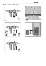
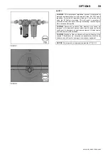
Page 61: ...OPTIONS 57 9 275 9 305 12 250 17 240 21 220 PRIMARY AND SECONDARY FILTER MAINTENANCE FIGURE 1 FIGURE 2 FIGURE 3 FIGURE 4 FIGURE 5 ...

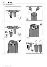
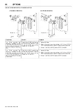
Page 62: ...58 OPTIONS 9 275 9 305 12 250 17 240 21 220 WATER SEPARATOR MAINTENANCE FIGURE 1 FIGURE 2 FIGURE 3 FIGURE 4 FIGURE 5 FIGURE 6 ...

Page 63: ...er levels causing overheating reduced engine life and reduced airend life CAUTION Excessively restricted filter elements may cause an increase in the amount of aerosol water and oil carryover which could result in damage to downstream equipment Normal service intervals should not be exceeded CAUTION Blockage of the condensate will result in flooding of the vessels If flooding occurs excessive cond...

Page 64: ...Q filters 2 Check all harness connections between IQ TCU and PT100 PT101 differential pressure sensors Repair harness as needed 3 If steps 1 and 2 checkout OK replace IQ TCU controller The TITAN controller has received a message over the J1939 CAN network from the IQ TCU controller indicating the IQ filters are restricting air flow past a usable level Code 52 is a FAULT condition and will stop the...

Page 65: ...sure Flow remains nominally constant Starting and stopping are unaffected by the selection and during normal running the selector switch may be safely operated Caution must be taken to ensure that downstream equipment is rated to suit the available pressure The pressure gauge indicates which setting has been selected A Standard regulation system B Dual Pressure regulation system 1 Dual Pressure So...

Page 66: ...p Operating with a load Operation and care of a new engine Engine shutdown Long term storage recommendations 77 PERIODICAL INSPECTION AND MAINTENANCE Lubricating system Cooling system Fuel system Air intake system Engine electrical Service and maintenance 82 COLD WEATHER OPERATION Cold weather Fuel selection Coolant Engine oil Battery Cold starting 84 MAINTENANCE SCHEDULE Maintenance schedule Expl...

Page 67: ...ars of trouble free and economical engine operation Should your engine require servicing please contact your nearest branch or distributor All information illustrations and specifications contained in this Manual are based on the latest product information available at the time of publication The company reserves the right to make changes in this Manual at any time without prior notice The picture...

Page 68: ...ilter 16 Dipstick location 17 Lubricating oil pan 18 Flywheel housing 19 Engine barring port 20 Turbocharger oil drain line 21 EGR cooler coolant supply 22 Exhaust manifold 1 Fuel rail pressure sensor 2 Intake manifold temperature and pressure sensor 3 Fuel rail 4 Fuel rail high pressure relief valve 5 Fuel drain line 6 Crankcase breather oil drain tubes 7 Fuel filter 8 Crankshaft speed sensor 9 S...

Page 69: ...haft Rotation viewed from front of engine Clockwise Displacement 8 9 litres 540 in3 Combustion type Direct injection No of cylinders bore x stroke mm in 6 114 x 144 5 4 49 x 5 69 Engine displacement L cid 8 9 540 Compression ratio 16 6 1 Firing order 1 5 3 6 2 4 Exhaust emission control system Engine modification Governor Electronic type Specified fuel Ultra Low Sulfur Diesel fuel ASTM D975 No 2 D...

Page 70: ...e and use radio frequency energy that if not installed and used properly can cause electromagnetic interference EMI conditions to exist between the accessory and Cummins electronic controlled fuel system Cummins is not liable for any performance problems with either the fuel system or the accessory due to EMI EMI is not considered by Cummins to be an engine failure and therefore is not warrantable...

Page 71: ...ency power output and sensitivity both base and remote site devices must be properly calibrated Obtain antenna reflective energy data measurements to determine the optimum antenna location Obtain optimum antenna type and mounting arrangement for your application Make sure your accessory equipment model is built for maximum filtering to reject incoming electromagnetic noise ...

Page 72: ...ith the check engine lamp alert the operator of the status of the aftertreatment diesel particulate filter The third additional indicator lamp indicates the position of the regeneration permit switch Ultra low sulfur diesel fuel is required for an engine equipped with an aftertreatment diesel particulate filter If ultra low sulfur diesel is not used the engine might not meet emissions regulations ...

Page 73: ...itiated by the equipment operator when not in operation Manual non mission regeneration requires an elevated engine speed of approximately 1000 to 1400 RPM The length of a manual non mission regeneration will vary depending on how full the aftertreatment diesel particulate filter is but will typically take anywhere from 45 minutes to 1 5 hours to complete A manual non mission regeneration can be i...

Page 74: ...rmance and durability Cummins Inc requires the use of a high quality SAE 15W 40 heavy duty engine oil such as CJ 4 or Euro ACEA E9 A sulphated ash limit of 1 0 mass percent is suggested for optimum piston deposit diesel particulate filter life and oil consumption control Special break in oils are not recommended for use in new or rebuilt Cummins engines Use the same lubricating oil that will be us...

Page 75: ...actors such as corrosion deposits and wear See the Engine Maintenance Schedule Section to determine which oil drain interval to use for the application Any warranty claims that could be oil quality related must be accompanied by complete service history details of the following prior to any warranty assessment being undertaken Oil type specifications and supplier Oil drain intervals Injector valve...

Page 76: ...d Shell have agreed that Chevron Texaco Shell Rotella and their private label counterpart Extended Life OAT coolants which do not meet the elastomer compatibility section of Cummins Engineering Standard 14603 are acceptable for extended service interval use assuming the initial coolant fill requirements were met from the vehicle s original equipment manufacturer OEM MidRange Heavy Duty and High Ho...

Page 77: ...system The use of sealing additives will Build up in coolant low flow areas Plug the radiator and oil cooler Possibly damage the water pump seal COOLING SYSTEM SOLUBLE OILS Do not use soluble oils in the cooling system The use of soluble oils will Corrode brass and copper Damage heat transfer surfaces Damage seals and hoses Sealing Additive ...

Page 78: ... glycol water Radiator Cap Condition After the replenishment of the coolant install the radiator filler cap Make sure the cap is securely installed Crankcase Breather Check and clean the breather tube daily during cold weather Battery Cable Connection Check the battery cable connections for looseness or corrosion A loosened cable connection will result in hard engine starting or insufficient batte...

Page 79: ...gine to run unloaded for extended periods so as to minimise the risk of cylinder bore glazing During operation pay attention to the following points if the engine shows any sign of abnormalities 1 Engine Oil Pressure The engine oil pressure is monitored by a switch that will stop the engine if the pressure falls below a pre set value If the oil pressure gauge shows below 10 psi 69 kPa or if the re...

Page 80: ... consult your local Doosan branch or dealer 6 State of the Exhaust Smoke Check for any abnormal exhaust smoke colour ENGINE SHUTDOWN General Information Close service valves Allow the engine to idle 3 to 5 minutes before shutting it off after a full load operation This allows adequate cool down of pistons cylinders bearings and turbocharger components Turn the ignition switch to the OFF position I...

Page 81: ...ilter Changes Oil leakage check Run the unit for five to ten minutes then visually check for oil leakage Oil level recheck Stop the engine for at least ten minutes Use the dipstick to recheck the oil level If necessary replenish with engine oil to the specified level Engine Oil Additives Engine oils contain a variety of additives Your engine should not need any extra additives if you use the recom...

Page 82: ...system with a mixture of sodium carbonate and water or a commercially available equivalent to the capacity or level stated in the OEM service manual Unless indicated otherwise by the OEM instructions it is critical that all shutoff valves be returned to their open positions once the system has been refilled and the deaeration process is about to begin This will help to make sure as much air as pos...

Page 83: ...moved Operate the engine at LOW idle for 2 minutes Turn off the engine and add plain water to bring the level back to FULL With the cooling system fill cap removed Start the engine Operate the engine at HIGH idle until the thermostat opens Allow the engine to return to LOW idle 2 minutes before shutting it down This allows adequate cool down of pistons cylinders bearings and turbocharger component...

Page 84: ...m the fuel system AIR INTAKE SYSTEM The air filter should be inspected regularly refer to the SERVICE MAINTENANCE CHART and the element replaced when the restriction indicator lamp illuminates The dust collector box es should be cleaned daily more frequently in dusty operating conditions and not allowed to become more than half full The safety element should be renewed every 2000 hours or every ot...

Page 85: ... connections will result in difficult engine starting or insufficient battery charge The battery cables must be tightened securely Never reverse and terminals when reconnecting cables after removal Even a short period of reverse connection will damage the electrical parts Cleaning of Battery When the battery terminals are fouled clean them with clean tepid water and wipe with a dry cloth to remove...

Page 86: ... be above 7 C 20 F Use Number 1 D if you expect temperatures below 7 C 20 F If Number 1 D is not available a winter blend of 1 D and 2 D is available in some areas during the winter months Check with your fuel supplier to be sure you get the correct blended fuel COOLANT Where the ambient temperature falls below freezing point the cooling system should be drained after engine operation but to elimi...

Page 87: ...r immediately before starting the engine COLD STARTING When operating in cold ambient conditions or when starting from cold If the engine does not start at the first attempt allow the battery to recover for at least 30 seconds Observe the following procedures In order to protect the starter do not engage for longer than 10 seconds during any attempt If during cranking the starter motor repeatedly ...

Page 88: ...00 2 years 5000 5000 4 years 1 Air Intake Piping Check O O 2 Fan Cooling Check O 3 Crankcase Breather Tube Check O 4 Air Tanks and Reservoirs Check O 5 Coolant Level Check O 6 Fuel Water Separator Drain O 7 Lubricating Oil Level Check O 8 Aftertreatment Exhaust Piping Check O 9 Dust Ejection Valve Check O 10 Air Cleaner Restriction Check O 11 Charge Air Piping Check O 12 Charge Air Cooler Check O ...

Page 89: ... Cummins Inc requires the use of a high quality heavy duty engine oil Use the following procedure for lubrication oil and recommendations Refer to the Fuels Lubricants and Coolants Section 18 Supplemental Coolant Additive SCA and Antifreeze Concentration Check Service interval is every oil change or 500 hours or 6 months whichever occurs first Use the following procedure for coolant specifications...

Page 90: ...s for your engine This will be valuable for customers that do not have easy access to the Cummins Electronic Parts Catalogue or the Cummins Parts Microfilm System Additional Features of the Customised Catalogue include Engine Configuration Data Table of Content Separate Option and Parts Indexes Service Kits when applicable ReCon Part Numbers when applicable ORDERING THE CUSTOMISED PARTS CATALOG Or...

Page 91: ... Incorrect injection timing Low cylinder compression pressure Engine fires but stalls immediately Air in the fuel system Compressor air inlet valve remains open during startup Unstable engine running Unstable low idling Crack in injection pipe Injection nozzle failure Uneven compression pressure between cylinders Engine malfunction in high speed range Insufficient fuel supply Air in the fuel syste...

Page 92: ...or nozzle misalignment Cylinder bore wear Insufficient air intake volume Air cleaner clogged Restricted air flow Excessive oil consumption Incorrect oil Wrong selection of type and viscosity Too much oil quantity Engine burning oil Faulty piston rings damaged cylinder bores Faulty valve stem seal Oil leakage Damaged seal Damaged turbocharger seal Loose joints gaskets Improper installation of filte...

Page 93: ...sive electrical loads Insufficient battery capacity for the application Aftertreatment Diesel Particulate Filter Excessive ash cleaning Electronic fault codes active or high counts of inactive fault codes View the fault codes on the compressor controller viewport Lubricating oil being used has high ash content Use an engine lubricating oil that meets CES 20081 Blending of engine lubricating oil in...

Page 94: ... replacing it Owner is not responsible for the labour needed to repair the part Owner is responsible for the cost of all parts required for the repair except for the defective Covered Part and any Covered Part damaged by a Warrantable Failure of the defective Covered Part Owner is responsible for the cost of lubricating oil antifreeze filter elements and other maintenance items replaced during rep...

Page 95: ...ou including diagnosis parts and labour MANUFACTURER S WARRANTY COVERAGE This warranty coverage is provided for 5 years or 3 000 hours of engine operation whichever first occurs from the date of delivery of the engine to the first user If any emission related part on your engine is defective the part will be repaired or replaced by Cummins Coverage This emission control system warranty applies onl...

Page 96: ... being available within 30 days or a repair not being complete within 30 days constitutes an emergency Replaced parts and paid invoices must be presented at a Cummins authorised repair facility as a condition of reimbursement for emergency repairs not performed by a Cummins distributor authorised dealer or other repair location approved by Cummins Warranty Limitations Cummins is not responsible fo...

Page 97: ...production HOW TO USE PARTS LIST a Turn to Parts List b Locate the area or system of the compressor in which the desired part is used and find illustration page number c Locate the desired part on the illustration by visual identification and make note of part number and description HOW TO ORDER The satisfactory ordering of parts by a purchaser is greatly dependent upon the proper use of all avail...

Page 98: ...rein are exclusive and the total liability of the Company with respect to this order whether based on contract warranty negligence indemnity strict liability or otherwise shall not exceed the purchase price of the part upon which such liability is based The Company shall in no event be liable to the Purchaser any successors in interest or any beneficiary of this order for any consequential inciden...

Page 99: ...e or information regarding your local distributor U S Latin America or Asia Pacific please contact Office hours Monday to Friday 8 00 a m to 5 30 p m EST Facility Telephone Fax Doosan Portable Power EMEA Aftermarket Drève Richelle 167 B 1410 Waterloo Belgium 32 2 404 0811 32 2 371 6915 Facility Telephone Fax Doosan International USA Inc 1293 Glenway Drive Statesville North Carolina 28625 9218 800 ...

Page 100: ......

Reviews: