OPTIONS
39
7/53
AFTERCOOLER AND WATER
SEPARATOR
OPERATING INSTRUCTIONS
The compressed air exits the separator tank through the top cover
piping, and will then travel into the aftercooler inlet side.
The aftercooler is cooled by the incoming compressor package air.
The compressed air and condensate (water with a small amount of
compressor lubricant) exits the aftercooler and enters the moisture
separator, where most of the condensate is removed.
At the bottom of the moisture separator a strainer and constant-bleed
orifice is fitted, which are sized to allow the maximum flow of
condensate while minimising compressed air loss.
A second condensate drain valve is mounted on the aftercooler body,
this valve will open on machine shutdown thereby allowing any
remaining condensate in the aftercooler to drain. This is to prevent
cooler damage at freezing temperatures.
These drains are plugged through the compressor frame and will expel
condensation to atmosphere. Should site contamination by this
condensate be prohibited, the user can connect an additional section
of drain hose and route into an allowed drain point.
MAINTENANCE
Daily Maintenance:
Verify, during full-load (maximum compressed air delivery) that
condensate can be seen to drain from the water separator drain hose.
Weekly Maintenance:
•
Verify that the piping from the orifice purge points are not clogged.
•
Clean the inside of the water separator housing.
Water separator maintenance:
•
With engine stopped, ensure pressure is relieved from air system.
•
Remove any hose connected to the water separator housing.
Inspect fittings and hoses for any blockage. Clean if necessary.
•
Remove and clean the water separator float.
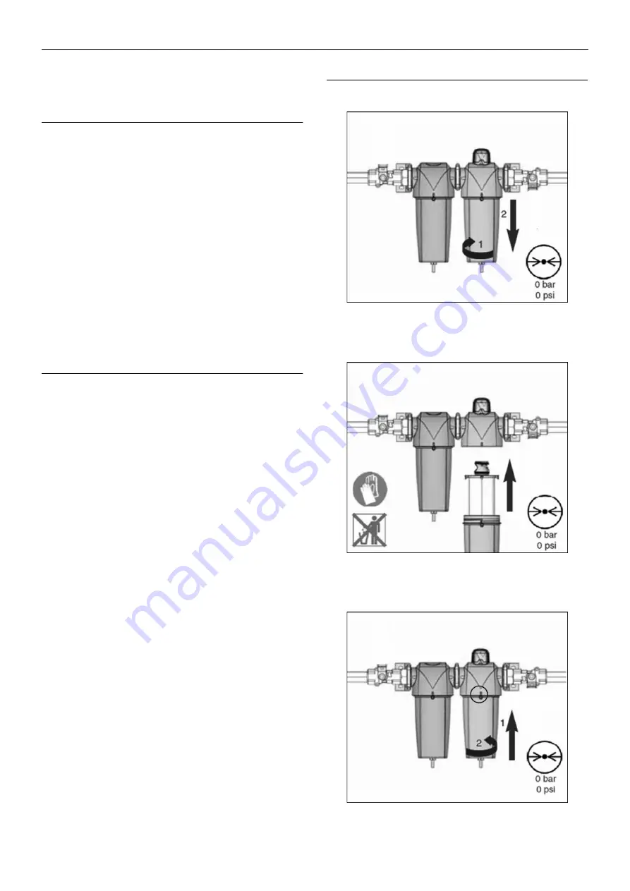
PRIMARY AND SECONDARY FILTER MAINTENANCE
(where used)
FIGURE 1.
FIGURE 2.
FIGURE 3.
Summary of Contents for 7/53
Page 2: ......
Page 4: ......
Page 11: ...DECALS 7 7 53 Engine oil drain...
Page 15: ...GENERAL INFORMATION 11 7 53 7 53 FIXED HEIGHT RUNNING GEAR 7 53 VARIABLE HEIGHT RUNNING GEAR...
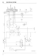
Page 34: ...30 ELECTRICAL SYSTEM 7 53 7 53...
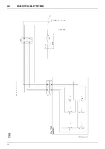
Page 36: ...32 ELECTRICAL SYSTEM 7 53 7 53...
Page 44: ...40 OPTIONS 7 53 WATER SEPARATOR MAINTENANCE FIGURE 4 FIGURE 5 FIGURE 1 FIGURE 2 FIGURE 3...
Page 58: ......
Page 59: ......
Page 60: ......

