OPTIONS
49
7/53
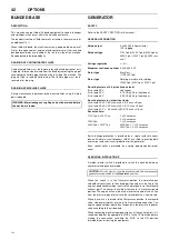
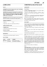
LUBRICATOR
SAFETY
GENERAL INFORMATION
Oil capacity:
2 litres
Oil specification:
Refer to the Tool Manufacturer’s Manual.
OPERATING INSTRUCTIONS
COMMISSIONING
Check the lubricator oil level and fill as necessary.
PRIOR TO STARTING
Check the lubricator oil level and fill as necessary.
MAINTENANCE
Check the lubricator oil level and replenish as necessary.
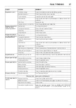
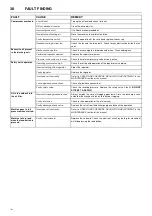
FAULT FINDING
OVERSPEED (CHALWYN) VALVE
MAINTENANCE
Three Monthly:
1) Disconnect intake pipework and release the valve from any support
brackets etc. to allow it to be removed.
2) Inspect the valve internally for cleanliness. If necessary, clean in
paraffin of white spirit taking normal precautions. Dry the valve
thoroughly.
3) Check there is no excessive wear and that the valve moves
smoothly over its complete operating stroke. DO NOT LUBRICATE.
4) Refit valve. Check valve setting.
Note:
The recommended routine maintenance period is three months.
This period is dependent on the operating conditions of the engine and,
by experience, may need to be varied.
ADJUSTMENT
Once the Chalwyn valve is installed, adjustment of the overspeed trip
setting is carried out using the adjuster and locknut. Basically rotating
the adjuster clockwise will increase the engine speed at which
automatic shut down occurs.
1) Start engine. Slowly accelerate. Note speed at which shut down
occurs.
2) Remove hose at air inlet to Chalwyn valve to expose the adjuster
and locknut.
3) Release locknut. Turn adjuster clockwise one turn. Tighten locknut.
4) Refit inlet hose to Chalwyn valve.
5) Start engine. Slowly accelerate. Note speed at which shut down
occurs.
6) Repeat the above steps ”2” to ”5” until the first setting at which the
engine does not shut down at high idle speed. Then either: A) Use the
results of shut down speed versus adjuster setting as a calibration
check to make a final adjustment to give the required setting (typically
10% to 15% over high idle) or B) if a very precise setting is not required,
turn the adjuster a further one turn clockwise to take the shut down
above high idle speed by a suitable margin. When using this setting
procedure it may be found that the engine occasionally shuts down
during the normal operation. If so, turn the adjuster clockwise by a
further one half turn.
7) Ensure the adjuster locknut is fully tightened.
Notes:
Turbocharged engines - when setting up a valve on a turbocharged
engine using the preceding method, it may be found that at high power
outputs, the engine will shut down at lower speed than required. If this
occurs, further small adjustment in step of one half turn clockwise
should be made until the problem is eliminated.
Jammed valve - if in the course of adjusting the valve it jams on its seat,
release by turning CLOCKWISE viewed from adjuster end of valve.
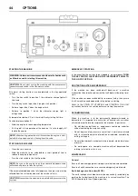
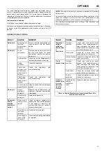
WARNING: Ensure that the lubricator filler cap is re-tightened
correctly after replenishing with oil.
WARNING: Do not replenish the lubricator oil, or service the lu-
bricator without first making sure that the machine is stopped
and the system has been completely relieved of all air pressure
(Refer to STOPPING THE UNIT in the OPERATING INSTRUC-
TIONS section of this manual).
CAUTION:
If the nylon tubes to the lubricator are disconnected then
ensure that each tube is re-connected in its original location.
FAULT
CAUSE
REMEDY
No oil flow.
Incorrect
connection.
Reverse the nylon tube
connections to the lubricator.
Summary of Contents for 7/53
Page 2: ......
Page 4: ......
Page 11: ...DECALS 7 7 53 Engine oil drain...
Page 15: ...GENERAL INFORMATION 11 7 53 7 53 FIXED HEIGHT RUNNING GEAR 7 53 VARIABLE HEIGHT RUNNING GEAR...
Page 34: ...30 ELECTRICAL SYSTEM 7 53 7 53...
Page 36: ...32 ELECTRICAL SYSTEM 7 53 7 53...
Page 44: ...40 OPTIONS 7 53 WATER SEPARATOR MAINTENANCE FIGURE 4 FIGURE 5 FIGURE 1 FIGURE 2 FIGURE 3...
Page 58: ......
Page 59: ......
Page 60: ......


