background image

This manual contains 
important safety information 
and must be made available to 
personnel who operate and 
maintain this machine.

46702181_en_A_06/17

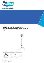
BALLOON LIGHT - LED 6x100W

OPERATION & MAINTENANCE MANUAL

Original Instruction

Summary of Contents for BALLOON LIGHT LED 6x100W

Page 1: ...l contains important safety information and must be made available to personnel who operate and maintain this machine 46702181_en_A_06 17 BALLOON LIGHT LED 6x100W OPERATION MAINTENANCE MANUAL Original Instruction ...

Page 2: ......

Page 3: ...or glove when handling lamps Oil from skin may damage the lamp during operation 8 Do not operate the Balloon Light with damaged electronics or if parts are missing 9 Do not operate the Balloon Light with a damaged envelope or without an envelope 10 All service must be performed by DOOSAN qualified personnel only See Warranty Info for details 11 Always use this lighting equipment at heights of at l...

Page 4: ...ts 8 Be sure that envelope is completely dry before installing the protective cover 9 Do not use chemical solvents to clean the envelope Use mild soap and water as necessary 10 Do not modify the electrical components or unit structure 11 Do not operate your Balloon Light if the cable is damaged twisted or tangled 12 Care must be taken to always operate the product with a filter as clean as possibl...

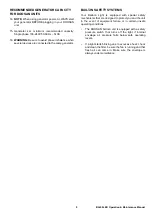
Page 5: ...generator BUILT IN SAFETY SYSTEMS Your Balloon Light is equipped with special safety mechanisms that are designed to protect you and the unit in the event of equipment failure or in certain unsafe operating conditions The DOOSAN balloon unit is equipped with a safety pressure switch that turns off the light if internal envelope air pressure falls below safe operating levels If a light starts blink...

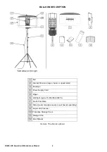
Page 6: ...ptional 1 Nut 2 Internal Structure cage base support stem 3 Envelope 4 Power Supply Cord 5 Zipper 6 LED light engine 10 85 058 6000 K 7 South Pole Plate 8 Stand recommended accessory purchased separately 9 Repair Kit 2 pieces 10 Protective Storage Cover 11 Storage Tube 12 User Manual ...

Page 7: ...2 Figure 3 Set the strap with its screws mounted aside Fig 3 Figure 4 Unplug the ground wire from the cage Fig 4 black arrow Unscrew the six nuts on the South Pole Plate inside the envelope Fig 4 white arrows Carefully remove the cage from the assembly Detach the old envelope from the assembly by sliding up along the equipment Put the envelope back in place Figure 5 Take care of the gasket DO NOT ...

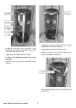
Page 8: ...urns only In order not to damage the screws use a 4mm Allen key Move the strap to the right and outside the vertical grid wire Engage the 5th screw and the 6th screw of the strap inside the holes of the heatsink Tighten these two screws for two turns only Proceed around the unit in the same way with the other screws located on the strap Stop before the two last holes of the strap that do not have ...

Page 9: ...screws fully through both sets of strap holes only by using a hexagonal screwdriver 4x50mm bit on a cordless screwdriver Place the two screws inside the holes of the heatsink without screwing them Tighten these two screws for two turns only In order not to damage the screws use a 4mm Allen key Model of cordless screwdriver to use type BOSCH GSR 10 8 2 LI with hexagonal screwdriver 4x50mm bit ...

Page 10: ...e torque setting of the available tool to 4 Nm Too high a torque setting may result in a twisted strap Too low a torque setting may result in the strap being too loose Figure 7 Loosely replace the nut on the top of the envelope Do not tighten until after the envelope is fully inflated Fig 7 Close the zipper Inflate the envelope Tighten the nut on the top of the envelope Fig 7 ...

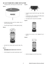
Page 11: ...velope zipper opening Figure 2 Unscrew the 12 screws which secure the strap Fig 2 Figure 3 Set the strap with its screws mounted aside Fig 3 Figure 4 Unplug the ground wire from the cage Fig 4 black arrow Unscrew the six nuts on the South Pole Plate inside the envelope Fig 4 white arrows Carefully remove the cage from the assembly Figure 5 Unscrew the six screws on the transparent cover Fig 5 Figu...

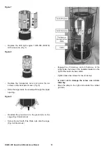
Page 12: ...he zipper opening Figure 9 Reattach the ground wire to the ground pin on the cage Fig 9 black arrow Screw the six South Pole Plate nuts onto the cage Fig 9 white arrows Engage the 3rd screw and 4th screw of the strap inside the holes of the heatsink located on the right of the inside harness cable Tighten these two screws for two turns only In order not to damage the screw use a 4mm Allen key Move...

Page 13: ...ew and the 6th screw of the strap inside the holes of the heatsink Tighten these two screws for two turns only Proceed around the unit in the same way with the other screws located on the strap Stop before the two last holes of the strap that do not have screws ...

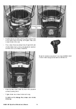
Page 14: ... screws fully through both sets of strap holes only by using a hexagonal screwdriver 4x50mm bit on a cordless screwdriver Place the two screws inside the holes of the heatsink without screwing them Tighten these two screws for two turns only In order not to damage the screws use a 4mm Allen key Model of cordless screwdriver to use type BOSCH GSR 10 8 2 LI with hexagonal screwdriver 4x50mm bit ...

Page 15: ...torque setting of the available tool to 4 Nm Too high a torque setting may result in a twisted strap Too low a torque setting may result in the strap being too loose Figure 10 Loosely replace the nut on the top of the envelope Do not tighten until after the envelope is fully inflated Fig 10 Close the zipper Inflate the envelope Tighten the nut on the top of the envelope Fig 10 ...

Page 16: ...he base in place On the P500TA slide the stand legs out from the folded position until the support bars are exactly horizontal When using your stands in windy conditions use the following weighting recommendations to keep your stand stable On the P500TA Fig 1 weights must be placed on each support at 20 in 50 cm from the centre of the stand Follow this correlation table Indicative for a flat floor...

Page 17: ...tch material Carefully place the patch onto the damaged part of the envelope firmly applying pressure to the areas of contact around the patch edge CLEANING THE AIR FILTER Remove sponge type air filter located under the south pole plate by sliding along the support stand Wash it or replace it Replace the clean air filter in the same way WARRANTY The envelope of the balloon is guaranteed for 6 mont...

Page 18: ... flux 50000 Lm Bulb number 6 Power by bulb 100 W Bulb type LED Bulb socket DOOSAN bulb socket Restrike type Restrike time 2 seconds Power supplied by exterior ballast No Colour temperature 6000 K Average bulb life 50000 h Protection type Pressure switch Breaker Fuse Anti vibration system Yes Envelope diameter 90 cm Envelope shape Tubular Weight 8 3 kg Max ambient temperature 45 C Power 610 W Power...

Page 19: ...19 BL600 LED Operation Maintenance Manual PARTS SECTION ...

Page 20: ...BL600 LED Operation Maintenance Manual 20 FRAME AND ENVELOPE ...

Page 21: ...21 BL600 LED Operation Maintenance Manual ITEM PART NUMBER DESCRIPTION QTY 1 46700839 Frame 1 2 46700821 Envelope 1 ...

Page 22: ...BL600 LED Operation Maintenance Manual 22 LEDs AND FAN ...

Page 23: ...nance Manual ITEM PART NUMBER DESCRIPTION QTY 1 46700836 Kit strap harness 1 2 46700828 Cover 1 3 46700840 Bracket upper 1 4 46700835 L E D 6 5 46700837 Bracket lower 1 6 46700832 Kit PE and CE 1 7 46700856 Guard 1 8 46700857 Fan 1 ...

Page 24: ...BL600 LED Operation Maintenance Manual 24 HOUSING AND BASEPLATE ASSEMBLY ...

Page 25: ...6 Spacer 4 4 46700823 Housing 1 5 46700851 Circuit board assembly 1 6 46700862 Kit foam 15 pieces 1 7 46700855 Fan 1 8 46700831 Kit cover and circuit breaker 1 9 46700858 Gasket 1 10 46700834 Plate lower 1 11 46700829 Ring 1 12 46700838 Spacer 1 13 46700825 Kit grip 1 14 46700842 Grid air filter 1 15 46700843 Baseplate and foot 1 ...

Page 26: ...BL600 LED Operation Maintenance Manual 26 CIRCUIT BOARD ASSEMBLY ...

Page 27: ...27 BL600 LED Operation Maintenance Manual ITEM PART NUMBER DESCRIPTION QTY 1 46700851 Circuit board assembly W Ref 2 4 1 2 46700845 Transformer 1 3 46700844 Sensor pressure 1 4 46700830 Motherboard 1 ...

Page 28: ...BL600 LED Operation Maintenance Manual 28 ELECTRICAL PLUGS VARIANTS ...

Page 29: ...tenance Manual ITEM PART NUMBER DESCRIPTION QTY 1 46700847 Cable 9 2 m long 1 2 46700849 Plug version FRD 1 3 46700850 Plug version CH 1 4 46700848 Plug version IEC 1 5 46700854 Plug version IEC UK 1 6 46700852 Plug version US 1 ...

Page 30: ...BL600 LED Operation Maintenance Manual 30 ACCESSORIES ...

Page 31: ...31 BL600 LED Operation Maintenance Manual ITEM PART NUMBER DESCRIPTION QTY 1 46700859 Container 1 2 46700826 Pouch 1 3 46702181 Manual 1 4 46700824 Kit inflatable 1 5 46700827 Kit repair 2 sheets 1 ...

Page 32: ...BL600 LED Operation Maintenance Manual 32 TELESCOPIC STAND OPTIONAL ...

Page 33: ... 1 3 46700869 Junction upper 1 4 46700866 Handle screw 3 5 46700865 Tube upper 1 6 46700871 Junction middle 1 7 46700870 Tube middle 1 8 46700864 Junction lower 1 9 46700868 Tube lower 1 10 46700867 Spider 2 11 46700873 Leg telescopic upper 3 12 46700874 Leg telescopic lower 3 13 46700863 Brace 3 14 46700872 Foot 3 15 46700875 Cap 3 ...

Page 34: ......

Page 35: ......

Page 36: ......

Reviews: