background image

- 142 -

154

9.5

6.25

15

139

15

1

2

3

4

5

6

A

B

C

D

E

F

G

H

J

K

L

M

N

P

7

8

9

:  DWC-2000
:  DC24V
:  65.11220-7006
:

826-1 Kuro 3-Dong, Duro-Gu Seoul 152-053 KOREA(DONG-IL TECKNO-TOWN)

Overspeed

ACTUATOR

Magnetic
Pick up

BATTERY

OPTIONAL  ACTUATOR
CABLE  SHIELDING TO
MEET  CE DIRECTIVE

ADD  JUMPER  FOR  12V
BATTERY  OR  ACTUATOR
CURRENTS  ABOVE  5A

AUX.

10V  POWER

FUSE
15A  MAX

SPEED TRIM
CONTROL-5K

CLOSE  FOR  IDLE

CLOSE  FOR  DROOP

Run

Crank

Reset

Starting
Fuel
Speed
Ramping

Run

Crank

Speed

Gain

Stability

Idle

Droop

Test

ON

OFF

ON

Autuator

Pic-up

Battery

Idle

Speed Trim

Droop

OFF

GHANA CONTROL

MADE IN KOREA

D1

D2

-      +

AUX   10V

32

CW

GND

EC8OM008 

Diagram 1. DWC-2000 Wiring and Outline 

Summary of Contents for D1146

Page 1: ......

Page 2: ...e CORRECT OPERATION and PROPER MAINTENANCE are essential In this manual the following symbols are used to indicate the type of service operations to be performed Removal Adjustment Installation Cleaning Disassembly Pay close attention Important Reassembly Tighten to specified torque Align the marks Use special tools of manufacturer Directional Indication Lubricate oil Inspection Lubricate grease M...

Page 3: ... Check and Adjust 3 4 Valves 3 10 Turbocharger 3 5 Lubrication System 3 11 Electrical Equipment 3 6 Air Cleaner 4 Commissioning and Operation 28 4 1 Preparation 4 4 Operation in Winter Time 4 2 Breaking in 4 5 Tuning the Engine 4 3 Inspections after Starting 5 Maintenance and Care 32 5 1 Periodical Inspection and Maintenance 5 5 Fuel System 5 2 Lubrication System 5 6 Injection Nozzle Maintenance 5...

Page 4: ...Maintenance 66 9 1 Engine Disassembly 9 3 Reassembly 9 2 Inspection 9 4 Breaking in 10 Maintenance of Major Components 121 10 1 Cooling System 10 3 Fuel Injection Pump 10 2 Lubricating System 10 4 Turbocharger 11 Special Tool List 167 Appendix Part After service center Applications for Doosan Engine ...

Page 5: ...st time read the operating instructions care fully and familiarize yourself with the critical points If you are unsure ask your DAEWOO rep resentative For reasons of safety we recommend you attach a notice to the door of the engine room pro hibiting the access of unauthorized persons and that you draw the attention of the operating personal to the fact that they are responsible for the safety of p...

Page 6: ...oil circuit during the operation The fluid which flow out can cause injury Fuel is inflammable Do not smoke or use naked lights in its vicinity The tank must be filled only when the engine is switched off Keep service products anti freeze only in containers which can not be confused with drinks containers Comply with the manufacturer s instructions when handling batteries CAUTION Accumulator acid ...

Page 7: ...5 minutes so that temperature equalization can take place Never put cold coolant into an overheated engine See Maintenance and care Do not add so much engine oil that the oil level rises above the max marking on the dipstick Do not exceed the maximum permissible tilt of the engine Serious damage to the engine may result if these instructions are not adhered to Always ensure that the testing and mo...

Page 8: ...gents creams etc or wear protective gloves Clean skin which has been in contact with engine oil Wash thoroughly with soap and water A nailbrush is an effective aid Certain products make it easier to clean your hands Do not use petrol Diesel fuel gas oil thinners or solvents as washing agents After washing apply a fatty skin cream to the skin Change oil soaked clothing and shoes Do not put oily rag...

Page 9: ...14 15 16 17 18 19 EA9O1001 1 Cooling fan 2 Vavle seat 3 Intake valve 4 Valve spring 5 Exhaust valve 6 Oil filter cap 7 Cylinder head 8 Combustion chamber 9 Pistion 10 Cylinder liner 11 Push rod 12 Tappet 13 Camshaft 14 Connecting rod 15 Crankshaft pulley 16 Vibration damper 17 Oil Pump 18 Oil suction pipe 19 Oil pan ...

Page 10: ...ew cross 6 EA9O1002 1 2 9 10 3 4 5 6 7 8 11 1 Fuel filter 7 Rocker arm 2 Intake manifold 8 Exhaust manifold 3 Injection nozzle assembly 9 Cylinder block 4 Valve cotter 10 Oil filter 5 Valve stem seal 11 Oil cooler 6 Valve guide ...

Page 11: ...nator 11 Oil drain valve 20 Fuel filter 3 Thermostat 12 Flywheel 21 Injection pump 4 Oil filter 13 Flywheel housing 22 Injection pipe 5 Oil filter cap 14 Cylinder head cover 23 Water pump 6 Exhaust manifold 15 Cooling water pipe 24 Mounting bracket 7 Vibration damper 16 Fuel pipe 25 Oil level gauge 8 Oil cooler 17 Starter 9 Cooling water pipe 18 Intake stake from radiator ...

Page 12: ...or Turbocharger to 3 Thermostat 11 Oil cooler Intake manifold 4 Oil filter cap 12 OIl drain valve 19 Intake manifold 5 Cylinder head cover 13 Flywheel housing 20 Fuel filter 6 Exhaust manifold 14 Flywheel 21 Starter 7 Breather 15 Exhaust elbow 22 Injection pump 8 Vibration damper 16 Turbocharger 23 Water pump 9 Oil filter 17 Cylinder head cover 24 Mounting bracket ...

Page 13: ...Oil cooler 18 Injection pump 3 Oil filter cap 10 Oil fan 19 Oil filter 4 Air pipe 11 OIl drain valve 20 Oil level gauge Turbocharger to 12 Starter 21 Air pipe Intake manifold 13 Flywheel housing Intercooler to Intake manifold 5 Turbocharger 14 Cylinder head 22 Mounting bracket 6 Exhaust elbow 15 Cooling water pipe 23 Water pump 7 Breather 16 Flywheel ...

Page 14: ...on timing B T D C static 18 18 12 12 Injection pump type Zexel in line AD type Zexel in line P type Governor type Mechanical governor Electrical governor type RSV type Ghana Control Injection nozzle type Multi hole type 5 hole Fuel injection pressure kg cm2 214 214 214 Compression pressure kg cm2 28 at 200 rpm Intake and exhaust valve clearance at cold mm 0 3 Intake valve Open at 16 C B T D C Clos...

Page 15: ...00 rpm 96 kW 105 kW 50 HZ 145PS 160 PS 1 500 rpm 107 kW 118 kW D1146T Standard 60 HZ 170 PS 187 PS 1 800 rpm 125 kW 138 kW 50 HZ 205 PS 240 PS 270 PS 1 500 rpm 151 kW 177 kW 199 kW Standard 60 HZ 253 PS 279 PS 303 PS P086TI 1 800 rpm 186 kW 205 kW 223 kW 50 HZ 203 PS 223 PS 1 500 rpm 149 kW 164 kW P086TI I 60 HZ 237 PS 260 PS 1 800 rpm 174 kW 191 kW Power Unit Engines Max Output rpm PS kW Naturall...

Page 16: ...Engine Number EA9O2002 DAEWOO HEAVY INDUSTRIES LTD MODEL SPEED 1500 1800 rpm STAND BY PRIME BORE mm mm cc STROKE VOLUME YEAR SERIAL NUMBER EA9O2003 IMPORTANT ENGINE INFORMATION DAEWOO HEAVY INDUSTRIES LTD ENGINE AND MATERIAL DIV 6 MANSECOK DONG DONG GU INCHEON KOREA TYPE 2 D DIESEL FUEL THIS DAEWOO HEAVY DUTY DIESEL MODEL EPA AND CARB STANDARDIZED ENGINE FAMILY DESIGNATION IS TUNE UP SPECIFICATION...

Page 17: ... crankshaft center line The engine has replaceable dry cylinder liners and indi vidual cylinder heads with struck in valve seat rings and replaceable valve guides 3 2 2 Piston con rod crankshaft The forged crankshaft is a ingrate type Counterweight is integrated with crank shaft body Radial oil seal on crankshaft and flywheel are provided to seal the flywheel housing inside pen etrations The con r...

Page 18: ...arranged at the front end 3 4 Valves The overhead valves are actuated via chilled cast iron tappets push rods and rocker armsfrom the camshaft 14 EA9O2004 Injection pump gear Z 54 Camshaft gear Z 54 Crankshaft gear Z 27 Oil pump idle gear Z 23 Oil pump drive gear Z 36 Idle gear Z 42 ...

Page 19: ... to the engine lubricating system The cylinder walls and timing gears are splash lubricated Each cylinder has an oil jet provided for cooling the underside of the pistons The lube oil is cleaned in a full flow oil filter D1146 D1146T P086TI PU086 PU086T 3 5 1 Oil cooler An oil cooler is provided between the oil filter and the cylinder block This cooler is a flat tube type with turbulence inserts a...

Page 20: ...very replacement of engine oil 3 6 Air Cleaner In case that elements are deformed dam aged or if the air cleaner has a crack replace it By the definite interval the elements must be cleaned and replaced Cleaning of air cleaner element Every 200 hours Changing of air cleaner element Every 400 hours 16 EA9O2005 Oil filter head Oil filter Cartridge EFM1002I ...

Page 21: ...ecification DIN 51601 DK For maximum fuel economy Number 2 D fuel when ever possible When temperatures are below 7 C 20 F use Number 1 D fuel If Number 1 D fuel is not available the mixture of one kerosene to two gallons of Number 2 D fuel can be used Once kerosene has been added the engine should be run for several minutes to mix the fuel 3 7 3 How to select fuel oil Fuel quality is an important ...

Page 22: ...5 Min F C Viscosity Kinematic D 445 1 3 2 4 1 9 4 1 1 8 10 CST 100 F 40 C Cloud Point F D 2500 See Note 1 See Note 1 See Note 1 Sulfur Content D 129 0 5 0 5 0 15 wt Max Carbon Residue D 524 0 15 0 35 0 1 on 10 wt Max Accelerated Stability D 2274 1 5 1 5 Total Insolubles mg 100 ml Max Ash wt Max D 482 0 01 0 01 Cetane Number Min D 613 45 45 45 Distillation D 86 Temperature F C IMP Typican 350 177 3...

Page 23: ...s which in the event of loss of coolant shut the engine down Check the coolant level of the expansion tank by removing the expansion tank filler cap and add coolant if necessary When injecting antifreeze solution first drain out the old coolant from the cylinder block and radiator and then clean them with cleaning solution Be sure to mix soft water with antifreeze solution 19 Reserve tank Radiator...

Page 24: ...d additive must be inspected every 500 hours to maintain it properly Note The proper density control of antifreezing solution and rust preventing additive will be able to prevent the rusting effectively and maintain the stable quality of engine For the improper control might give the fatal damage to the cooling water pump and cylin der liners detail care is needed Since D1146 PU086 D1146T PU086T a...

Page 25: ... yellowish green or so with the green color indication of test paper storage bottle confirm the density Then the density indication must be in the hue range of 33 to 50 6 The brown at the middle of test paper and the lower pink color indication represent the additive state for rust prevention and the proper range is that the meeting numerical value of brown vertical and pink color horizontal locat...

Page 26: ...en the fan pulley and the alternator pulley in normal condi tion For the adjustment of the tension loosen the adjusting bolts which support the alternator adjust the tension and tight en the bolts again 22 Water pump pulley Press here V belt Alternator pulley 10 15mm Crank pulley EA9O2006 EA9O2007 ...

Page 27: ...ft draws in fresh air and delivers it at a higher pressure to the cylinders The turbocharger is naturally air cooled Lubrication of the main bearing is by oil under pres sure from the engine lubricating system 23 EA603004 1 Compressor casing A Air inlet 2 Turbine casing B Gas outlet 3 Compressor wheel C Gas inlet 4 Impeller D Oil supply 5 Turbine E Oil return C 5 3 2 B E 4 1 A D ...

Page 28: ...OIL PRESS W R SW 65 27441 7006 STARTER 65 26201 7063 ALTERNATOR 65 26101 7120 OVER HEAT W R SW 67 27441 6008 STANDARD LOW OIL PRESS W R LAMP OVER HEAT W R LAMP CHARGE LAMP OPTION STANDARD STANDARD POS STANDARD KEY SWITCH 60 25501 7003 HEAT OFF ON START TML B C BR R1 R2 ACC 5 0 SQ 5 0 SQ 5 0 SQ 5 0 SQ 60 SQ 60 SQ 0 85 SQ 0 85 SQ 0 85 SQ 0 85 SQ 0 85 SQ E G EARTH EA8O3006 P TAB KET GP 890545 TACHOME...

Page 29: ...closed current flows and the engine is started After the engine starts the pinion automatically returns to its initial position when the starting key switch is released Once the engine starts the starting key switch should be released immediately Otherwise the starter motor may be damaged or burned out In case of repairing the engine dip the pinion of the starter and ring gear into the fuel and re...

Page 30: ... P086TI 24V X 6 0kW 26 TERMINAL B M10 x P1 5 TERMINAL S W M5 x P0 8 EA8O3008 24V x 6 0kW 2 5A 20o C 24V M EA8O3009 Motor S W KS S W S W S B B M Wiring Diagram 24V x 6 0kW ...

Page 31: ...moisture WARNING Always disconnect the battery earth cable before starting work on the electrical system Connect up the earth cable last as there is otherwise a risk of short circuits 27 50 EA9O2010 30 MAGNET SWITCH STARTER MOTOR STARTER S W 24V X 4 5kW EA902009 Wiring Diagram ...

Page 32: ...ration of a new engine Break in Because the sliding surfaces of a new engine are not lapped enough the oil film can be destroyed easily by overload or overspeed and the engine life time may be shortened Therefore the following things must be obeyed by all means Up to the first 2 000 km 150 hours Engine should be run at fast idling until the temperature of the engine becomes normal oper ating condi...

Page 33: ...fter break in When starting a cold engine always allow the engine to warm up gradually Never run the engine at full throttle until the engine is thoroughly warmed up Be sure to check the oil level frequently during the first 50 hours of operation since the oil consumption will be high until the piston rings are properly seated 4 3 Inspections after Starting During operation the oil pressure in the...

Page 34: ...the freezing of cooling water and the viscosity of lubricating oil 4 4 1 Prevention against the freeze of cooling water When not using anti freeze completely discharge the whole cooling water after engine run ning The freeze of cooling water causes the fatal damages of the engine Because the anti freeze is used to prevent cooling water from freeze consult The amount of anti freeze 4 4 2 Prevention...

Page 35: ...aved and more lasting results will be obtained by following a definite and thorough pro cedure of analysis and correction of all items affecting power and performance Economical trouble free operation can better be ensured if a complete tune up is performed once every years preferably in the spring Components that affect power and performance to be checked are Components affecting fuel injection N...

Page 36: ...and engine wear Refill and drain oil pan every 50 hours of operation or 6 months whichever occurs first At the end of the break in peri od 50 hours change the oil sump oil and replace the oil filter 5 2 2 Oil level Check the oil level in the engine sump daily with a dipstick The notches in dipstick must indicate the oil level between the max and the min permissible The oil level should be checked ...

Page 37: ...n order to circulate oil through lubrication system Thereafter shut down the engine After waiting for about 10 minutes measure the quantity of oil and refill the additional oil if necessary Recommend of lubricating oil Initial factory filling is high quality break in oil API Service CH 4 grade During the break in period 50 hours check the oil level frequently Somewhat higher oil consumption is nor...

Page 38: ...il filter cartridge can be seated properly Lightly oil the O ring and turn the oil filter until sealing face is fitted against the O ring Turn 1 1 4 turns further with the filter wrench NOTE It is strongly advisable to use DAEWOO genuine oil filter cartridge for replacement 34 EA9O2005 Oil filter head Oil filter Cartridge SAE 20 20W SAE 10W SAE 30 SAE 40 50 SAE 10W 30 SAE 5W 20 SAE 15W 40 SAE 10W ...

Page 39: ...re cap b Open the drain valve at the radiator lower part to drain the coolant as the right fig ure c Loosen the coolant drain plug Loosen the coolant drain plug of the cylinder block and oil cooler CAUTION When removing the pressure filler cap while the engine is still hot cover the cap with a rag then turn it slowly to release the internal steam pressure This will pre vent a person from scalding ...

Page 40: ...mechanically contaminated gray or black signs of a leakage on the water pump casing clean the cooling system prior to removing that water pump as follows a Drain coolant b Remove thermostats so that the whole cooling system is immediately flown through when cleaned c Fill the cooling system with a mixture of potable water and 1 5 by volume of cleaner Henkel P3T5175 d Warm up engine under load Afte...

Page 41: ... is decreased and engine malfunction is occurred So you always check whether the intake air systems like air filter element are worn or polluted Cleaning In order to maintain the heat transfer efficiency of the intercooler it is necessary to clean it at regular intervals Cleaning of intercooler fins Every 600 hours 37 EA5O4003 Air air intercooler with downstream radiator Combined radiator Cooling ...

Page 42: ...he filter is installed horizontally watch for top mark on cleaner bowl 5 4 2 Changing filter element CAUTION Do not allow dirt to get into the clean air end On removing the hexagon nut take out the dirty cartridge and renew or clean Wipe the cleaner housing with a damp cloth in particular the sealing surface for the element NOTE Unless the maximum number of cleanings up to 5 x have been done the f...

Page 43: ...be dry before it is reinstalled Never use steam sprayers petrol gasoline alkalis or hot liquids etc to clean the filter elements Knocking out dirt by hand In emergencies when no compressed air or cleaning agent is available it is possible to clean the filter cartridge provisionally by hitting the end disk of the cartridge with the ball of one s thumb Under no circumstances should the element be hi...

Page 44: ... it counter clockwise with filter wrench Discard the used filter Remove the fuel filter thread adapter seal ring Use a clean lint free cloth to clean the gasket surface of the fuel filter head Install the new thread adapter seal ring aa supplied with the new filter Use clean oil to lubricate the filter seal aa and fill the new filter with clean fuel Install the filter on the filter head Tighten th...

Page 45: ...ion of injection pump after loosening the air removing screws of cartridge filter respectively remove the air by operating the manual pump of fuel supply pump until bubble will disap pear Fuel supply pump Every time of engine oil replacement the fuel strainer installed at the fuel supply pump should be removed and cleaned 5 5 4 Fuel contamination and water trap In the generator environment the mos...

Page 46: ...ding plug screw After the whole air is pulled out close the plug screws of the filter and the pump Confirm the resistance of fuel delivery by repetition pressing of the feed pump cap Pressure and turn the priming pump cap simultaneously to close it 5 5 7 Injection pump Check the fuel injection pump housing for cracks or breaks and replace if damaged Check and see if the lead seal for idling contro...

Page 47: ...essure does not meet the specified limit Check nozzle spray patterns and replace if damaged CAUTION The injection lines are designed for high operating pressures and should thus be handled with particular care When mounting the pipes to the engine take care of good fitness Do not bend pipes to permanent deformation not for replacing the nozzles either Do not mount any heavily bent pipes Avoid bend...

Page 48: ...n acid solvent if necessary using a plastic scraper If the air compressor should be badly fouled it is recommended that the wheel be allowed to soak in a vessel with solvent and to clean it then with a stiff brush In doing so take care to see that only the compressor wheel is immersed and that the turbocharger is supported on the bearing casing and not on the wheel 5 7 2 Special hints It is recomm...

Page 49: ... 45 EA4M2018 Dial gauge Magnetic vise Oil inlet Move the turbine shaft in both directions simultaneously Radial play Limit of wear 0 57mm ...

Page 50: ...e where the flywheel is mounted but cylinder No 6 begins from the front side of the engine on the contrary Step 1 After letting the cylinder No 6 in the overlap TDC position by turning the crankshaft adjust the valves corresponding to of following figure At this time cylinder No 1 should be at the ignition TDC position O T Step 2 After adjusting upper valves turn the crank pulley 360 to adjust the...

Page 51: ...nsert a thickness gauge of 0 3mm between valve stem aaand rocker arm aa 3 Turn the adjusting bolts aa using a screw driver until the gauge can be pulled out with some restriction 4 After the adjustment fix the adjusting bolt not to rotate and tighten the lock nut at the same time 5 Measure the clearance one more time and if necessary adjust again 47 Model Intake Valve Exhaust Valve D1146 PU086 D11...

Page 52: ... notch mark of the right figure cor responding to the injection timing is aligned with the pointer on the fly wheel housing Turn the timer until the notch mark of the indicator plate attached to the fuel injec tion pump is aligned with the notch mark of the timer 48 Notch mark EA9O5002 Injection timing notch mark Timing check hole Flywheel ring gear EA9O5001 D1146 PU086 P086TI D1146T PU086T Fuel i...

Page 53: ...pter in nozzle holder hole and connect the com pression pressure gauge to the adapter 3 Cut off fuel circulation rotate the starter then measure compression pressure of each cylinder Testing conditions at water temperature of 20 C and speed of 200 rpm 10 turns 49 EA9O5003 EA9O5004 Standard value 25 28 kg cm2 Limit 24 kg cm2 or less Difference between each cylinders Within 10 EAMD021I Torque 6 0 6 ...

Page 54: ...a V belt tension tester 4 Measuring tension Lower indicator arm 1 into the scale Apply tester to belt at a point midway between two pulleys so that edge of contact surface 2 is flush with the V belt Slowly depress pad 3 until the spring can be heard to disengage This will cause the indicator to move upwards If pressure is maintained after the spring has disengaged a false reading will be obtained ...

Page 55: ...s and nuts To change the V belts loosen fixing bolts and nuts Then push the alternator toward water pump pulley by hand 51 EA9O2007 Tensioning forces on the tester Type Drive belt width new installation When servicing after Installation After 10 min long running time running time M 9 5 mm 50 kg 45 kg 40 kg A 11 8 mm 55 kg 50 kg 45 kg B 15 5 mm 75 kg 70 kg 60 kg C 20 2 mm 75 kg 70 kg 60 kg ...

Page 56: ...eakage for intercooler hoses clamp Intake Clean and change Exhaust the air cleaner element System Clean the inter cooler air fins Clean the turbo charger Check the leakage fuel line Clean the fuel strainer of fuel feed pump Remove sediment from fuel tank Fuel Drain the water in separator System Replace the fuel filter element Check fuel Injection timing Check the injection nozzles Check the state ...

Page 57: ...7 2 Trouble Shooting 53 ...

Page 58: ... 54 ...

Page 59: ... 55 ...

Page 60: ... 56 ...

Page 61: ... 57 ...

Page 62: ... 58 ...

Page 63: ... 59 ...

Page 64: ... Replace piston ring Injection timing incorrect Adjust Fuel injection amount insufficient Adjust injection pump Nozzle injection pressure Adjust or replace improper or stuck Supply pump s function lowered Repair or replace Fuel pipe system clogged Repair Air suction amount insufficient Clean or replace air cleaner Supercharger poor Repair or replace 2 Output insufficient Compression pressure insuf...

Page 65: ... Replace bearing progress the oil clearances increase grind crankshaft Lopsided wear of crankshaft Grind or replace Oil supply insufficient due to oil Clean oil passage passage clogging Stuck bearing Replace bearing Grind 2 Con rod and Con rod Lopsided wear of con rod bearing Replace bearing bearing Lopsided wear of crank pin Grind crankshaft Connecting rod distortion Repair or replace Stuck beari...

Page 66: ...p 7 Oil Consumption Excessive Clearance between cylinder Replace 1 Oil level elevated liner piston Wear of piston ring ring groove Replace piston piston ring Piston ring s damage stick wear Replace piston ring Piston ring opening s disposition Correct position improper Piston skirt part damaged or Replace piston abnormal wear Oil ring s oil return hole clogged Replace piston ring Oil ring s contac...

Page 67: ... discard ed and new ones should be prepared for installation as normal function of the parts can not be maintained if these parts are reused 7 To facilitate proper and smooth reassemble operation keep disassembled parts neatly in groups Keeping fixing bolts and nut separate is very important as they vary in hardness and design depending on position of installation 8 Clean the parts before inspecti...

Page 68: ...r and fuel which was injected through multi nozzles in the combustion chamber This engine by means of Toroidal Combustion Mode has the specific character such as quiet and stable revolutional motion multi purpose application economical fuel and oil consump tion etc 8 2 2 OMEGA combustion bowl D1146T P086TI The OMEGA combustion bowl is a unit designed to perform high efficiency low emission combust...

Page 69: ...rown is normally necessary to pre vent crown cracking and ring sticking The design of the gallery the design and location of the oil spray nozzle and the quantity of oil flowing in the gallery are critical in order to achieve the desired temperature reduction The cross section shape of the gallery should be designed to achieve sufficient oil movement to maximize cooling effi ciency 65 EA7M1001 ...

Page 70: ... 9 1 2 Oil level gauge Pull out the oil level gauge 9 1 3 Cooling water Remove the radiator cap Open the drain plug at the radiator lower part to drain the coolant as the right figure Caution When removing radiator filler cap while the engine is still hot cover the cap with a rag then turn it slowly to release the internal steam pressure This will prevent a person from scald ing with hot steam spo...

Page 71: ...ge fixing bolts then take off the flange and cooling fan 9 1 6 V belt Remove the V belt by loosening the alternator tension adjusting bolt and tighten the bolt 9 1 7 Starter Loosen the starter assembling nuts and remove the starter being care ful not to damage its gears 67 EA9O4001 EA9M3001 EA9O2007 ED7OM003 Drain cock Tension adjusting ...

Page 72: ...r 9 1 9 Breather Loosen the clamp screw to remove the rubber hose 9 1 10 Intercooler P086TI only Tear down the various hoses and air pipes from the inter cooler Remove the intercooler fixing bolts and tear it down 9 1 11 Alternator Remove the alternator fixing bolts and disassemble the alternator Remove the tension adjusting bolts and bracket 68 ED7OM009 EA6M2001 EA9M3004 ...

Page 73: ...assembling nuts and disassemble it 9 1 13 Oil filter Remove the oil filter assembling bolts and disassemble the oil filter assembly 9 1 14 Water pump Remove the water pump assem bling bolts and disassemble the water pump 9 1 15 Cylinder head cover Remove the head cover assem bling bolts and lift the cover 69 EB8M3002 ED7OM008 EB5M3012 ...

Page 74: ...bled Pull the seal ring out through the noz zle hole of cylinder head and scrap it 9 1 17 Turbo charger D1146T PU086T P086TI Disassemble the oil supply pipe that supplies oil from cylinder block to turbo charger and the oil discharge pipe that discharges oil from turbo charger to cylinder block Remove the turbo charger assembling nuts and disassemble it from the exhaust manifold 9 1 18 Exhaust man...

Page 75: ...ly Caution Be careful for the gasket pieces not to get in the passage of cooling water 9 1 21 Rocker arm Remove the rocker arm bracket assembling bolts in the reverse order zigzag method of assembling and disassemble the rocker arm Disassemble the push rod 9 1 22 Cylinder head Remove the cylinder head bolts in the reverse order of tightening but remove it step by step First step Loosen 1 2 threads...

Page 76: ...e any damage on the contact surfaces 9 1 23 Oil pan Remove the oil pan assembling bolts and disassemble the pan After removing the oil pan gasket scrap it 9 1 24 Vibration damper Remove the vibration damper assem bling bolts in the reverse order of assembling and disassemble the damper assembly 9 1 25 Timing gear case cover Disassemble the oil seal using an oil seal removing jig Remove the cover f...

Page 77: ...assemble the upper lower of con necting rod caps by tapping lightly with urethane hammer and remove the bearing By pushing the connecting rod with wooden bar from the direction of oil pan toward cylinder head disassem ble the piston assembly The disassembled piston assembly should be handled to prevent bumping each other and stored as the cylin der s order In order for connecting rod cap not to be...

Page 78: ...the piston ring with a plier 4 Clean the piston thoroughly 9 1 28 Cylinder liner Disassemble the cylinder liner with a special tool or hand but be careful not to generate any damage at cylinder block 9 1 29 Gear and idle gear pin Remove the camshaft gear assem bling bolts and disassemble the camshaft gear 74 EAMD088I EAMD087I EDM2025I ...

Page 79: ... for lubrica tion Remove the injection pump flange assembling nuts Remove the bracket fixing bolts of injection pump and disassem ble by pulling the injection pump backward 9 1 31 Water chamber cover Remove the assembling bolts and disassemble the water chamber cover Remove the remnant gasket thoroughly 75 EAMD021I EAMD022I ...

Page 80: ...l housing Disassemble the oil seal of fly wheel housing 9 1 34 Injection pump drive gear Remove the assembling nuts of drive gear Remove the drive gear housing ass embling nuts and disassemble the gear assembly 9 1 35 Timing gear case Remove the timing gear case assem bling bolts By tapping lightly with a urethane ham mer the right and left back of tim ing gear case s connecting part dis assemble ...

Page 81: ...t to be prevented from bends or damage put it on the special lathe and store Disassemble the metal bearings in turn and store them Note Do not mingle with the metal bearings and bearing caps randomly To prevent mix ing temporarily assemble the metal bearings to the corresponding bearing caps in turn 9 1 38 Camshaft and tappet In order for camshaft not to be dam aged disassemble turning it In order...

Page 82: ...9 1 39 Oil spray nozzle D1146T P086TI only Remove the valve screws of oil injec tion nozzle and disassemble it 78 ...

Page 83: ...ssembly disassembly 1 Disassemble the cylinder assembly and put it on the shelf for assembly or clean lathe Caution Prevent any damage to gasket s contact surface of the cylinder head 2 Disassemble the cotter pin spring spring seat pushing valve spring by a special tool 3 Pull out the intake and exhaust valves 4 The disassembled parts are kept laid in turn 5 Disassemble the valve stem seal 6 By me...

Page 84: ...of cylinder head s intake and exhaust manifolds with horizontal ruler and clearance gauge 4 The hydraulic test The hydraulic test of cylinder head is same as the cylinder block test 3 Inspection of valve and valve guide 1 Valve After cleaning valve with fuel check it Valve stem outer diameter Measure the valve stem outer diameter at 3 positions top middle and bottom and check for any wear and if b...

Page 85: ...nt If the clearance is excessive measure the valve and replace the excessively worn valve or valve guide Valve stem end play Assemble the valve at cylinder head s valve guide and see if it is centered with the valve seat using a special tool 81 Dimension Standard Limit Description Intake valve stem 8 950 8 970 mm 8 93 mm Exhaust valve stem 8 935 8 955 mm 8 91 mm EFM2037I Dimension Standard Limit D...

Page 86: ...seat For the disassembling of valve seat by welding the welding bead to a valve seat rotating tool or valve seat pull it out with a special tool For the assembling of a new valve seat by putting it among the dry ices of an ice box pre viously for about 2 hours for the cold shrinkage and press it in the cylinder head by a special tool bench press Apply valve lapping compound to the valve head seati...

Page 87: ...eds the spec ified limit the valve spring must be replaced Valve spring tension Use a spring tester to measure the valve spring tension if the measured value is less than the specified limit the valve spring must be replaced 83 EA3M2033 Spring free Length Standard Intake valve 64 mm Exhaust Inner 60 mm valve Outer 71 mm Inclination Free length EJM2050I Square unit mm Standard Limit Valve Spring In...

Page 88: ... valve spring with a special tool After installing the valve check whether the valve is correctly installed or not tap ping it lightly with urethane hammer 9 2 3 Rocker arm assembly 1 Disassembly 1 Disassemble the snap rings that are located at both ends of rocker arm shaft by a plier 2 Disassemble in the order of washer rocker arm bracket rocker arm spring rocker arm 2 Inspection of rocker arm as...

Page 89: ...th a considerable amount of step wear should be replaced Rocker arm bushing diameter Measure the inside diameter of the rock er arm bushing with an inside microme ter or vernier calipers and compare the measured values with the rocker arm shaft diameter If the clearance exceeds the limit replace either bushing or shaft whichever worn more 3 Tappet and push rod Clearance Measure the clearance of th...

Page 90: ...it replace tappets Push rod run out Use a feeler gauge to measure the push rod run out Roll the push rod along a smooth flat surface as shown in the figure 4 Reassembling rocker arm assembly Reassembling can be done in the reverse order of disassembling and following things should be heeded Check the oil supply hole of rocker arm shaft for any clog and clean thoroughly Be careful not to occur any ...

Page 91: ...tch or damage Slight step wear or damage on the cam face may be corrected with oil stone or oiled grind ing paper But replace if severely damaged 3 Cam shaft Clearance between camshaft journal and camshaft bush With an outside micrometer measure the camshaft journal diameter Measure the inside diameter of the camshaft bushing on the cylinder block using a cylin der bore indicator and compare the m...

Page 92: ...t 1 Defect check By naked eyes check for any scratch or damage on the crankshaft journal and crank pin By means of magnetic particle test and color check check the crankshaft for any crack and if found replace it 2 Wear measuring With an outside micrometer measure the diameter of the crankshaft journals and pins in the directions as shown and compare the measured values to determine the amount of ...

Page 93: ...e bearings available Standard 0 25 Inside diameter is 0 25 mm lesser than the standard size 0 50 Inside diameter is 0 50 mm lesser than the standard size 0 75 Inside diameter is 0 75 mm lesser than the standard size 1 00 Inside diameter is 1 00 mm lesser than the standard size Undersize bearings are available in 4 dif ferent sizes as indicated above and the crankshaft can be reused through the reg...

Page 94: ...ankshaft and bearing Method 1 dial gauge Main bearing clearance Install the main bearing in the cylinder block tighten the bearing cap to speci fied torque then measure the inside diameter C o m p a r e t h e t w o v a l u e s o b t a i n e d through measurement of main bearing i n s i d e d i a m e t e r w i t h t h e o u t s i d e diameters of crank shaft journals to determine the oil clearance ...

Page 95: ...s and pins ground and install undersize bearings 2b Oil clearance between crankshaft and bearing Method 2 plastic gauge Assemble the crankshaft on the cylinder block and put plastic gauge on the journal and pin of crankshaft and then after assembling bearing cap tighten the bolts at the specific torque Again after disassembling the bearing cap by removing the bolts take out the flatted plas tic ga...

Page 96: ...eassembly operation Crankshaft bearing crush Install the bearing and cap in the cylinder block retighten the bolts to specified torque unscrew out one bolt completely then measure the clearance between the bearing cap and cylinder block using a feeler gauge 92 O A Spread O A O B O B EDM2047I EAMD063I Standard 0 19 0 22 mm ...

Page 97: ...2 6 Piston assembly 1 Disassemby of piston assembly Disassemble piston according to the disassembly process of 3 1 28 Piston 2 Piston inspection 1 Visual check Visually check the pistons for cracks scuff or wear paying particular attention to the ring groove 2 Clearance between the piston and cylinder liner With an outside micrometer measure the piston outside diameter at a point 13mm away from th...

Page 98: ...learance is beyond the specified limit Clearance between piston and liner 3 Piston rings 1 Visual check Replace the piston rings with new ones if detected worn or broken when the engine is overhauled 2 Piston ring gap Insert the piston ring into the upper por tion of the cylinder liner bore so that it is held at a right angle to the cylinder liner wall Measure the piston ring gap with a feeler gau...

Page 99: ... piston ring tension Replace the piston ring if the measured value is beyond the limit 4 Piston pin inspection 1 Wear Measure the amount of wear on the piston pin at the points as shown The measured values are beyond the limit 0 08 mm or greater replace the pin EA0M4032 Feeler gauge Standard Limit Top ring 2nd ring 0 07 0 102 mm 0 15 mm Oil ring 0 05 0 085 mm 0 15 mm Standard Top ring 2 58 3 88 kg...

Page 100: ... connecting rod tester and check for distortion using a feeler gauge If the con necting rod is found distorted never re use it but replace with a new one 2 Holes alignment parallelism Measure the alignment of the connecting rod piston pin bushing holes with connecting rod big end holes At this time also use both connecting rod tester and feeler gauge 3 Wear Assemble the connecting rod to the crank...

Page 101: ...ssembled Check the bolts for looseness after reassembly After completing the engine reassembly operation check if there is missing parts or short age of parts Keep your hands clean during the working 9 3 2 Cylinder block Cover the floor of the workshop with wood plate or thick paper to prevent damage to the cylinder head and place the cylinder block with the head fitting surface facing downward 9 ...

Page 102: ...e camshaft Caution Be careful not to generate a damage to camshaft and bush Check to see that the camshaft rotates smoothly 9 3 5 Crankshaft Install the main bearing refer to assemble sequence right figure machined with two holes in the cylinder block so that the key is aligned with the key groove then apply oil to the bearing surface 98 EDM2060I EA0M4083 Oil port and passage Key groove EFM2061I 7...

Page 103: ...t at both sides of the crankshaft apply engine oil to journals and pins then assemble the crankshaft with the cylinder block by tightening the fixing bolts Caution Coat engine oil to the pin and journal of crankshaft Install the oiled thrust washers with the oil groove facing outward Install the bearing and thrust washers to the bearing cap and apply oil to the bearing and thrust washers 99 EAMD07...

Page 104: ...h impact wrench tighten up to about 15 kg m 4 Fourth stage With torque wrench tighten up to about 25 kg m 5 Fifth stage By means of torque wrench tighten finally in the specified torque 30 kg m Tighten the bearing cap in the sequence of 4 3 5 2 6 1 7 Check to see that the assembled crankshaft turns smoothly 9 3 6 Flywheel housing Temporarily install the guide bar on the cylinder block Apply gasket...

Page 105: ...and adjust 9 3 7 Rear oil seal Apply lubricating oil to the outside of the oil seal and flywheel housing inside diameter and fit them over the crank shaft then assemble the oil seal using an oil seal fitting jig 9 3 8 Flywheel Installation of flywheel ring gearWith a gas burner heat the ring gear evenly until heat expansion takes place then install it using a hammer Caution Do not allow the temper...

Page 106: ...ho sensor Pick up sensor Move the lock nut to hexagonal side of sensor completely Rotate CW the tacho sensor on fly wheel housing until the end of it reach on fly wheel ring gear Rotate CCW the tacho sensor for 270 gap 1 0 mm and fix lock nut Tolerance limit is 27 gap 0 1 mm 9 3 10 Water chamber cover Coat the adhesive over the water cham ber cover Particular around bolt holes and after attaching ...

Page 107: ... the cylinder liner dried up and push it into the cylinder block by hand Wet the liner inside diameter with engine oil 9 3 12 Piston and connecting rod Use a piston heater to heat the piston approximately 100 C 212 F for 5 minutes Align the piston pin hole with the oiled connecting rod small end and press the piston pin by lightly tapping with a rub b e r h a m m e r t o a s s e m b l e t h e conn...

Page 108: ...d portion face upward The surface marked as Y is upper surface Adjust the angle among individual piston r i n g g a p s t o 9 0 a n d f i t a p i s t o n assembling jig onto the piston Use care not to match the ring gaps with the pin direction Install the bearing by aligning it with the connecting rod key groove and apply oil to the bearing and piston Position the valve seating surface toward the ...

Page 109: ...nd tighten them to the specified torque using a torque wrench as follows Tightening order 1 First stage Coat engine oil over bolts 2 Second stage Temporary bolt screwing about 1 2 threads 3 Third stage With torque wrench tighten up to about 10 kg m 4 Fourth stage With torque wrench tighten up to about 15 kg m 5 Fifth stage By means of torque wrench tighten finally in the specified torque 18 kg m M...

Page 110: ... the bolts tighten primarily the bolts of both end parts and then do the rest 9 3 14 Timing gear and idle gear pin Install the oil pump idle gear onto the No 7 bearing cap With the oil port on the idle gear pin facing the cylinder block install the idle gear pin Idler gear pin with oil hole is assembled toward cylinder block Install a thrust washer over the camshaft and assemble the cam gear by al...

Page 111: ...ointer to the 19 position of the engraved scale After adjusting the injection timing of fuel injection pump drive gear tighten the fix ing bolts in the direction of fuel injection pump 9 3 16 Injection pump Install the injection pump bracket in the cylinder block After measuring the amount of run out with an alignment setting jig disassemble the bracket adjust the shims then reassemble it 107 EA9M...

Page 112: ... holder and then on it assemble the pipe of U shape on it Operating the priming pump of supply pump turn the crankshaft slowly in the direction of engine rotation until the fuel will drop at the rate of a drop for 6 8 sec Confirm then whether the indication point at the flywheel housing inspection hole and the engraved specified injection angle are coincided or not and if the injection timing is n...

Page 113: ...ark of the indicator plate attached to the fuel injection pump is aligned with the notch mark of the coupling Tighten the Coupling fixing bolts and nuts to specified torque Install the oil delivery pipe and return pipe 9 3 17 Oil pump and oil pipe Install a dowel pin in the No 7 bearing cap then assemble the oil pump by tap ping lightly with urethane hammer Insert the lock washers and tighten the ...

Page 114: ... new oil seal on the oil seal hole of timing gear case cover aligning the center of them then assemble the oil seal using an oil seal fitting jig 9 3 20 Timing gear case cover Install dowel pin on the timing gear case Mount a gasket by aligning the fixing bolt holes with those on the gasket Align the dowel pin with the cover pin hole then install the cover with light tap Tighten the fixing bolts b...

Page 115: ...r b l o c k a n d t h e con tacting part of flywheel housing by means of a scraper Caution Be careful for the gasket pieces not fall into the engine during the work Coat the silicone at the gasket part that was removed Contacting part and attach the new oil pan gasket Assemble the oil pan by tightening the oil pan assembling bolts and when tighten ing bolts primarily tighten the bolts 4ea at the b...

Page 116: ... at the oil hole of the oil cooler housing and insert the O ring Assemble the oil cooler assembly by tightening the assembling nuts Connect the cooling water pipe with the cooling water pump and tighten a hose clamp 9 3 25 Starter Assemble the starter in position on the flywheel housing 9 3 26 Intake and exhaust valves Identify the marks of IN and EX impressed on the valve head before assembling t...

Page 117: ...that the valve is assembled correctly 9 3 27 Cylinder head Blow the bolt holes of cylinder block with a compressed air and remove the foreign matter Clean the head gasket contact surface thoroughly Caution However be careful for the foreign mat erial not to enter into the combustion chamber Assemble the new head gasket by align ing the holes with dowels of cylinder block with TOP mark facing upwar...

Page 118: ... Head Bolts However before tightening bolts the side parallel degree between cylinder heads should be adjusted Tightening order of bolts by steps 1 First stage Coat the bolts with engine oil 2 Second stage Tighten 1 2 threads with hands 3 Third stage Tighten at about 6 kg m with a wrench 4 Fourth stage Tighten at rotating angle method 180 with a wrench 5 Fifth stage Finally tighten at rotating ang...

Page 119: ...screws and push the feeler gauge of specified value between a rocker arm and a valve stem to measure the clearance of the valve and rocker arm contacting part and adjust the clearance with adjust ing screw respectively and then tighten with the lock nut As for the valve clearance adjust it when in cold Caution 1 Crankshaft revolution is done by hands without using a starting motor 2 Turn it to the...

Page 120: ...ne at the specified value using zigzag method Semi install valve clearance adjusting bolts onto the rocker arm Install the spring rocker arm bracket rocker arm spring washer and snap ring in the described sequence Install the rocker arm and bracket in the same direction 9 3 29 Intake manifold Put in the new gasket between the cylinder head and manifold and assemble the intake manifold by tightenin...

Page 121: ...bolts is from the middle to left and right alternately Caution For upper and lower bolts differ in the length so use the correct bolts 9 3 31 Turbocharger for D1146T PU086T P086TI Fit a new gasket over the stud bolts of the exhaust manifold before tightening those turbocharger fixing bolts Install the oil supply pipe and return pipe Tighten the clamps of rubber hose that is connected air pipe to t...

Page 122: ...rrow impressed on the fuel filter head so that fuel can be fed in the sequence of FUEL FEED PUMP FUEL FILTER FUEL INJECTION PUMP 9 3 35 Injection nozzle Install the dust seal with its round portion facing downward Mount a seal ring on the seal ring seating surface of the cylinder head and assemble nozzle holder assembly with the nozzle pipe installing direction facing outward Be sure to follow the...

Page 123: ...r head cover Assemble the new gasket with the cylinder cover install the cover on the cylinder head then tighten the fixing bolts in sequence to specified torque Assemble the breather hose with PCV valve Insert the oil filler cap in the cylinder head cover 9 3 38 Cooling fan Install the fan drive pulley onto the timing gear case cover Install the fan flange and cooling fan onto the cooling water p...

Page 124: ...auge Apply sealant Locktite 262 to the bot tom side of the guide tube Then assemble the guide tube and oil level gauge on the oil pan 9 3 41 Others Assemble by connecting the other oil and fuel hoses 9 4 Breaking in Refer to Breaking in in chapter of Commissioning and Operation 120 Water pump pulley Press here V belt Alternator pulley 10 15mm Crank pulley EA9O2006 EQM3005I ...

Page 125: ...he cylinder block and water passage of the cylinder head to absorb the heat of the com bustion chamber The water absorbing the oil heat and combustion chamber heat goes on to the thermostat through the water pipe and circulates to the water pump if water temperature is lower than the valve opening temperature on the thermostat while circulating to the radiator at water temper ature higher than the...

Page 126: ...that the coolant is forced to flow into the radia tor 122 Item D1146 T P086TI PU086 T 1 Water pump Type Centrifugal type Delivery About 150 liter min About 190 liter min Pump speed 1 800 rpm 2 200 rpm Pumping back pressure 0 5 bar 2 Thermostat Operating temperature 71 C Valve lift 8 mm or more at 85 C Operating temperature 71 85 C 3 Cooling fan and belt D1146 T PU086 T 590mm 6 Fan diameter Number ...

Page 127: ...s for handling The wax pallet type thermostat does not react as quickly as bellows type one to a varia tion of temperature of coolant Such relatively slow reaction is mainly due to the large heat capacity of the wax pellet type thermostat Therefore to avoid a sharp rise of coolant tem perature it is essential to idle the engine sufficiently before running it In cold weather do not run the engine a...

Page 128: ...ing into water jacket Replace cylinder head gasket due to broken cylinder head gasket 2 Engine overcooling Thermostat inoperative Replace thermostat Ambient temperature too low Install radiator curtain 3 Lack of coolant Radiator leaky Correct or replace Radiator hoses loosely Retighten clamps or replace connected or damaged hoses Radiator cap valve spring Replace cap weakened Water pump leaky Repa...

Page 129: ...fications Lubricating system Forced pressure Oil filter type Full flow circulation Oil pump type Gear type Bypass for filter element Relief valve opening pressure 10 1 5 kg cm2 Valve opening pressure 1 8 2 3 kg cm2 Bypass for oil cooler Bypass for entire oil filter Opening pressure 5 1 kg cm2 Valve opening pressure 4 0 4 8 kg cm2 Adjusting valve for spray nozzle Opening pressure 1 5 1 8 kg cm2 CYL...

Page 130: ... cover is fixed with the two dowel pins 3 Disassemble the drive gear and driven gear Inspection and correction 1 With steel rule and feeler gauge measure the axial end play of the oil pump gear Replace if the measured value is beyond the limit 2 With a feeler gauge measure the amount of backlash between the oil pump drive gear and driven gear Replace if the measured value is beyond the limit 126 E...

Page 131: ... 1 Oil consumption Poor oil Use suggested oil excessive Oil seal or packing leaky Replace Pistons or piston rings worn Replace pistons and or piston rings Cylinder liner worn Replace cylinder liner Piston rings sticking Replace pistons and or piston rings Valve guide oil seals or valve Replace guides or valve stem worn 2 Oil pressure too low Poor oil Use suggested oil Relief valve sticking Replace...

Page 132: ...cause the deterioration of the engine Make sure that servicing should be performed at the professional maintenance shop as authorized by Bosch or Zexel Company For adjustment of fuel injection volume refer to the Specifications of fuel injection pump described on the following pages 128 Fuel return pipe Fuel filter Fuel hose Nozzle opening pressure Overllow valve Valve opening pressure 1 6kgf cm2 ...

Page 133: ...6 0 600 mm Test oil ISO4113 Temperature 40 5 C Nozzle holder Ass y 65 10101 6026 Nozzle 5 x 0 29 B Engine standard parts 65 10101 7050 214 kg cm2 Injection pipe ID OD L 65 10301 6048 2 x 6 650 mm Rack diagram and setting valve at each point Rack Pump Injection Q ty on RIG Standby power Check position speed mm3 1 000st Press point mm rpm A Test condition B Engine mmHg for inj Pump standard parts A ...

Page 134: ... 7 Governor adjustment D1146 130 EA9M4002 0 Injection Pump Speed rpm Rack Position mm 2 4 6 8 10 12 14 C D B A ...

Page 135: ...mm Test oil ISO4113 Temperature 40 5 C Nozzle holder Ass y 65 10102 6026 Nozzle 5 x 0 29 B Engine standard parts 65 10101 7050 214 kg cm2 Injection pipe ID OD L 65 10301 6048 2 x 6 650 mm Rack diagram and setting valve at each point Rack Pump Injection Q ty on RIG Standby power Check position speed mm3 1 000st Press point mm rpm A Test condition B Engine mmHg for inj Pump standard parts A 900 114 ...

Page 136: ... 7 Governor adjustment D1146T 132 EA9M4002 0 Injection Pump Speed rpm Rack Position mm 2 4 6 8 10 12 14 C D B A ...

Page 137: ...pump Injection pipe ID OD L 2 2 x 6 35 650 mm Test oil ISO4113 Temperature 40 5 C Nozzle holder Ass y 65 10102 6049 Nozzle 5 x 0 34 B Engine standard parts 65 10101 7055 214 kg cm2 Injection pipe ID OD L 65 10301 6049 2 2 x 6 35 650 mm 65 10301 6052 Rack diagram and setting valve at each point Rack Pump Injection Q ty on RIG Standby power Check position speed mm3 1 000st Press point mm rpm A Test ...

Page 138: ... 10101 7050 214 8 kg cm2 Injection pipe ID OD L 6 x 2 2 650 mm Rack diagram and setting valve at each point Rack Pump Injection Q ty on RIG Refer to 3 Rack Diagram Check position speed mm3 1 000st Press point mm rpm A Test condition B Engine mmHg for inj Pump standard parts A 10 5 1100 88 5 2 2 5 Full B 7 7 370 11 5 2 25 Idle C 100 135 Balance Weight 740g Lever ratio min max 1 1 2 Governor spring ...

Page 139: ...gram 135 14 C B 10 5 7 7 6 9 0 370 485 5 _ 5 _ 30 20 1100 1215 or LESS 1165 or more than 14 Pump speed RPM Idling serve spring Stroke start Governor spring set Idling serve Spring setting EDM5001I Rack position mm ...

Page 140: ...rts 65 10101 7050 214 8 kg cm2 Injection pipe ID OD L 6 x 2 2 650 mm Rack diagram and setting valve at each point Rack Pump Injection Q ty on RIG Refer to 3 Rack Diagram Check position speed mm3 1 000st Press point mm rpm A Test condition Max Var mmHg for inj Pump Bet Cyl A 10 5 1100 113 5 2 2 5 Full B 7 9 370 11 5 2 25 Idle C 100 Balance Weight 740g Lever ratio min max 1 1 2 Governor spring k 7 2...

Page 141: ... 1 3MM st 0 5 mm 0 _ 30 20 C Rack position mm 14 0 or more 14 0 10 5 R 2 7 0 R 1 0 1 7 7 11 2 0 485 1100 30 1190 30 1165 400 370 C Q 17 B A Pump speed RPM Governor spring setting Booster compensating start 10 Idling serve spring setting ...

Page 142: ...g No Description Q ty Remark 1 Frame 1 2 Bearing retainer kit Ass y 1 3 Mounting bar 1 8 SWP connector 1 Mg610320 11 Front cover 1 T3 2 13 Shaft 1 15 Return spring guide Ass y 1 16 Oil seal 1 SC 0283 E0 17 Allen screw 8 M5 x 0 8 x L12 23 Manual stop device Ass y 1 30 Stop plate 1 T3 2 52 Return shaft Ass y 1 54 Stop level 1 62 Lead wire LG 16AWG 63 Corrugate tube Dia 10 L250 10 ...

Page 143: ...e adjustments gain and stability All adjustments are accessible from the front cover The primary features of the DWC 2000 Series speed control unit are the engine STARTING FUEL and SPEED RAMPING adjust ments The use of these features will minimize engine exhaust smoke experienced prior to attain engine operating speed The speed control unit also includes other features such as adjustable droop and...

Page 144: ...eased with clockwise rotation of the gain adjustment The gain adjustment has a non linear range of 33 1 The stability adjustment when advanced clockwise increases the time rate of response of the governor system to match the various time constants of a wide variety of engines The speed control unit is a PID device the D derivative portion can be varied when required See Instability section During ...

Page 145: ...Supply 24VDC Battery System Transient and Reverse Voltage Protected Polarity Negative Ground Case Isolated Power Consumption 50 mA continuous plus actuator current Maximum controllable actuator current at 25 C Inductive Load 10 A continuous Magnetic Speed Sensor Signal 1 120 V RMS Reliability vibration 1G 20 100 Hz Testing 100 Functionally Tested Physical Dimensions See Outline Dia 1 Weight 705 gr...

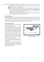
Page 146: ...ATOR CABLE SHIELDING TO MEET CE DIRECTIVE ADD JUMPER FOR 12V BATTERY OR ACTUATOR CURRENTS ABOVE 5A AUX 10V POWER FUSE 15A MAX SPEED TRIM CONTROL 5K CLOSE FOR IDLE CLOSE FOR DROOP Run Crank Reset Starting Fuel Speed Ramping Run Crank Speed Gain Stability Idle Droop Test ON OFF ON Autuator Pic up Battery Idle Speed Trim Droop OFF GHANA CONTROL MADE IN KOREA D1 D2 AUX 10V 32 CW GND EC8OM008 Diagram 1...

Page 147: ... stray speed sig nals may be introduced to the speed control unit With the engine stopped adjust the gap between the magnetic speed sensor and the ring gear teeth The gap should not be any smaller than 0 020 in 0 45mm Usually gear tooth will achieve a satisfactory air gap The magnetic speed sensor voltage should be at least 1 VAC RMS during cranking 4 Adjustments Before starting engine Confirm the...

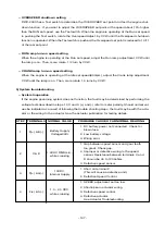
Page 148: ... Then back off slightly CCW 1 8 turn beyond the point where stability returns Excellent performance should result from these adjustments If instability cannot be corrected or further performance improvements are required refer to the sec tion on SYSTEM TROUBLESHOOTING Starting fuel adjustment The engine s exhaust smoke at start up can be minimized by completing the following adjustments A Place th...

Page 149: ...ent control When the engine is at idle speed the speed control unit applies droop to the governor system to insure stable operation Speed droop operation Droop is typically used for the paralleling of engine driven generators Place the optional external selector switch in the DROOP position DROOP is increased by clockwise rotation of the DROOP adjustment control When in droop operation the engine ...

Page 150: ... governor system accessories Up to 20ma of current can be drawn from this supply Ground reference is Terminal G Caution a short circuit on this terminal can damage the speed control unit Wide range remote variable speed operation Simple and effective remote variable speed can be obtained with the DWC 2000 Series control unit A single remote speed adjustment potentiometer can be used to adjust the ...

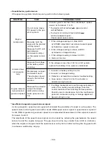
Page 151: ...em Inoperative If the engine governing system does not function the fault may be determined by performing the voltage tests described in steps 1 2 3 and 4 and refer to meter polarity Should normal val ues be indicated as a result of following the trouble shooting steps the fault may be with the actu ator or the wiring to the actuator See the actuator publication for testing details 147 STEP TERMIN...

Page 152: ...0VDC a SPEED adjustemnt set above desired speed b Defective speed control unit 2 If the voltage reading is above 6 0VDC a Actuator or likage binding 3 if the voltage reading is below 4 0VDC 4 Gain set too low If the voltage is less than 15V for a 24V system replace the battery if it is weak or undersized 1 Actuator or battery wiring in error 2 Actuator or linkage binding 3 Defective actuator See a...

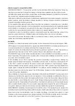
Page 153: ...C type can be further classified as fast or slow instability Fast instability is a 3Hz or faster irregularity of the speed and is usually a jitter Slow periodic instability is below 3Hz can be very slow and is sometimes violent If fast instability occurs this is typically the governor responding to engine firings Raising the engine speed increases the frequency of instability and vice versa In thi...

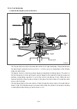
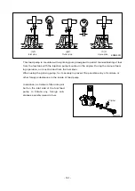
Page 154: ...and tappet via the camshaft of injection pump and performs reciprocating operation to control the suction and delivery of fuel When the cam reaches the Bottom Dead Center as shown in the figure the fuel is drawn in through the check valve on the inlet side The fuel pressurized as the cam rotates on flows through the check valve on the outlet side as shown in B If the feeding pressure increases abn...

Page 155: ... must be bled from the fuel lines When using the priming pump fix it securely to prevent the possible entry of moisture or other foreign substances in the inside of feed pump In addition a strainer is fitted into joint bolt on the inlet side of the fuel feed pump to filtrate any foreign sub stances possibly mixed in fuel 151 A Inlet side B Outlet side C Interruption EQM4020I EB1M4003 Strainer ...

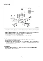
Page 156: ...ng then take off the tappet 10 and push rod 1 3 Inspection If the check valve is damaged or scored on its seat face replace it with a new one Inspect the piston and tappet for damage Replace the push rod if excessively worn and replace together with the pump housing if required The inspection for wear should be performed in the same procedure as for suction pressure test described below 4 Reassemb...

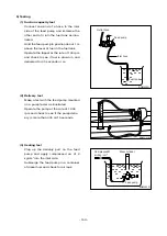
Page 157: ...red for 40 seconds or so 2 Delivery test Make a test with the feed pump mounted on a pump tester as illustrated Operate the pump at the rate of 1 000 rpm and check to see if the pump deliv ery is more than 405 cc 15 seconds 3 Sealing test Plug up the delivery port on the feed pump and apply compressed air of 2 kg cm2 into the inlet side Submerge the feed pump in a container of diesel fuel and chec...

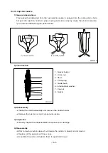
Page 158: ...e nozzle assembly and remove the nozzle holder Remove the nozzle nut and components inside 4 Inspection Visually inspect the disassembled components for damage 5 Reassembly After removing carbon deposit submerge the nozzle in diesel oil and clean it Replace all the gaskets with new ones Assemble the parts and tighten them to specified torque 1 At valve closed 2 At valve opened EQM4024I 1 2 4 5 7 8...

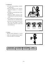
Page 159: ... After adjusting the injection pressure tighten the cap nut to specified torque Re check the injection pressure and see if the spray pattern is normal Spray pattern should be uniform and free of spattering 7 Testing With the nozzle assembled to a nozzle tester and specified pressure applied check the nozzle for fuel leakage 155 EFM2056I EFM2057I Abnormal Normal Abnormal EAMC022I Engine Model D1146...

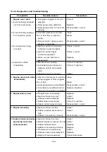
Page 160: ...ce between nozzle and needle valve injection pressure incorrect Adjust 2 Engine starts but stalls Pipe from feed pump to injection Clean immediately pump clogged or filter clogged Air in fuel Bleed Feed pump delivery insufficient Disassemble correct Fuel delivery insufficient due to Replace breather clogging of fuel tank air breather 3 Engine lacks power Plunger worn excessively Replace Injection ...

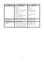
Page 161: ...es defective Disassemble correct Injection starting pressure of Adjust each barrel incorrect Automatic timer defective Disassemble correct 7 Engine does not reach Nozzles not working normally Disassemble correct maximum speed Governor defective Disassemble correct 8 Engine idling unstable Movement of control rod Disassemble correct sluggish Operation of plungers unsmooth Disassemble correct Contro...

Page 162: ...pressure at 50Hz Approx 0 76 kg cm2 50Hz Approx 1 56 kg cm2 compressor outlet 60Hz Approx 1 00 kg cm2 60Hz Approx 1 76 kg cm2 At maximum Air suction volume 50Hz Approx 8 2 m3 min 50Hz Approx 13 0 m3 min output 60Hz Approx 10 3 m3 min 60Hz Approx 16 4 m3 min Speed of turbine 50Hz Approx 72 000 rpm 50Hz Approx 102 000 rpm revolution 60Hz Approx 78 000 rpm 60Hz Approx 110 000 rpm Maximum allowable sp...

Page 163: ... Seal ring 19 Screw 6 Seal ring 21 Heat dissipator 7 Seal ring 22 Compressor housing 8 Compressor wing wheel 23 Clamp 9 Turbine housing 24 Bolt 10 Bolt 27 Liquid gasket 11 Clamp 30 Loctite 13 Bearing housing 31 Liquid anti burn agents 14 Retainer ring 22 24 15 19 14 18 16 17 13 21 11 10 27 30 31 7 4 8 6 2 5 9 1 3 EFM3001I 23 ...

Page 164: ...ged into cylinders of given capacity the greater engine output can be obtained as a greater volume of air charged into the cylinders burns so much more fuel As explained the compressing of air to supply into the cylinders is called Supercharging and the making use of the energy of exhaust gas discharged from the combustion chamber to charge the compressed air into the cylinders is called Turbochar...

Page 165: ...hat the shaft is not devi ated from its the original position due to this thrust 2 Journal bearing This journal bearing of floating type forms a dual oil film on both the inside and outside of the bearing so that the bearing can rotate independently As the dual oil film plays a role as a damper the sliding speed of the bearing surface becomes lower than the rotating speed of the shaft resulting in...

Page 166: ... oil fluidity within the pipes can be deteriorated Immediately after starting 1 Run the engine at idle for 5 min utes after starting off 2 Check each part for leakage of oil gas and air and take proper mea sure 1 Applying load abruptly If load is abruptly applied with the engine a n d t u r b o c h a r g e r r o t a t i n g unsmoothly such parts that a suffi cient amount of oil has not reached can...

Page 167: ...as from discharge pipes turbocharger fixing portions etc lowers charging effect As such components as turbine chamber that becomes red hot during operation use heat resisting steel nuts do not interchange these nuts with ordinary steel nuts In addition apply anti seizure coating to fixing nuts on the portions as designated 3 Fuel system If the full load stopper regulating the maximum injection vol...

Page 168: ... slowly If a high pitch sound is heard contin uously it means that the rotor assembly is not normal In this case as the metal bearing and rotor are likely to be in abnormal conditions the turbocharger should be replaced or repaired 2 Guide for checking rotor end play Disassemble the turbocharger from the engine then check the rotor axial play and radial play When disassembling the turbocharger be ...

Page 169: ... the journal and thrust bearings by rotating them with hand Clean not only the pipes installed between the engine and oil inlet port but also the oil outlet pipe and check them for damage or foreign matters Assemble each joint on oil pipes securely to prevent oil leaks 2 Intake system Check the inside of the intake system for foreign matters Assemble each joint on the intake duct and air cleaner s...

Page 170: ...rect 2 Excessive white smoke 1 Oil leak into turbine and compressor Disassemble repair or replace 2 Worn or damaged seal ring due to excessive Disassemble repair wear of bearing or replace 3 Low engine output 1 Gas leak at each part of exhaust system Check and correct 2 Air cleaner element restricted Replace or clean 3 Turbocharger fouled or damaged Disassemble repair or replace 4 Leakage at disch...

Page 171: ...jection pump setting ass y for D1146 T PU086 T Injection pump setting ass y for P086TI EF 123 127 EF 123 173 Oil seal CR insert ass y Front Up to 2000 Apr Oil seal NOK insert ass y Front From 2000 May EF 123 043 EF 123 184 Oil seal CR insert ass y Rear Up to 2000 Apr Oil seal NOK insert ass y Rear From 2000 May EF 123 052 EF 123 317A Oil seal CR puller ass y Front Up to 2000 Apr Oil seal NOK pulle...

Page 172: ...No Figure Tool Name 10 EF 123 065 Valve spring press 11 EU 2 0647 Crankshaft gear punch 12 EF 120 208 Piston sleeve 13 60 99901 0027 Feeler gauge 14 T7610001E Snap ring plier 15 T7621010E Piston ring plier EB1M7001 ...

Page 173: ...30 kg m Balance weight fixing bolt M12 x 1 5 10 9T 9 0 kg m Flywheel housing fixing bolt M14 x 1 5 10 9T 8 0 kg m Flywheel fixing bolt M14 x 1 5 10 9T 18 0 kg m Crankshaft pulley fixing bolt M12 x 1 5 10 9T 13 4 kg m Oil spray nozzle M14 x 1 5 8 0 kg m Major Parts Screw Strength Tightening Torque Remarks Diameter x pitch grade Injection nozzle nut M28 x 1 5 7 0 0 5 kg m Injection pump bracket bolt...

Page 174: ... 78 1 2 1 3 1 4 1 95 2 35 M8 0 7 0 75 1 1 1 1 4 1 25 1 9 2 1 2 2 3 1 3 8 M8 x 1 0 73 0 8 1 2 1 1 1 5 1 34 2 1 2 3 2 4 3 35 4 1 M10 1 35 1 4 2 2 1 9 2 7 2 35 3 7 4 2 4 4 6 2 7 4 M10 x 1 1 5 1 6 2 5 2 1 3 1 2 8 4 3 4 9 5 7 8 4 M12 2 4 2 5 3 7 3 3 4 7 4 2 6 3 7 2 7 5 10 5 12 5 M12 x 1 5 2 55 2 7 4 3 5 5 4 6 6 8 7 7 8 11 2 13 4 M14 3 7 3 9 6 5 2 7 5 7 10 11 5 12 17 20 M14 x 1 5 4 1 4 3 6 6 5 7 8 3 7 5...

Page 175: ... 110 801 Replace liner away from lower 110 959 surface of piston Clearance between 0 041 0 221 0 3 Replace one worn piston and liner more Width of Top ring 3 50 Replace piston if Piston piston ring 2nd ring 3 06 3 08 groove width is beyond grooves Oil ring 4 04 4 06 specified value Piston projection from Measure unworn cylinder block upper 0 0 12 Must exist portion beneath the surface rim of the u...

Page 176: ...08 0 110 tightening metal cap and releasing one stud Oil seal for wear crank Replace oil seal Major shaft rear if oil leaking moving End play of con rod 0 170 0 248 0 50 Replace con rod parts Clearance between con rod bearing and crank 0 034 0 098 0 25 Replace bearing pin Clearance between Measure after small end bush 0 050 0 081 0 12 installing the bearing piston pin and releasing one bolt Connec...

Page 177: ...en valve stem and valve 0 15 Without spring seat head Free length Approx 64 Valve Tension force Intake when pressed 67 9 72 1 66 5 Replace valve to 41mm kg valve spring spring Squareness along free 2 5 Valve length direction system Free length Approx 60 Tension force when 26 9 30 3 Replace pressed to valve spring 38mm kg Squreness along free 2 5 C Exhaust length valve direction spring Free length ...

Page 178: ...055 0 105 of oil pump gear Replace gear Clearance between or cover drive gear shaft 0 032 0 077 oil pump cover hole Clearance between Replace bush drive gear shaft and 0 040 0 094 or cover Lubricating Oil cover hole system pump Diameter of gear shaft 16 950 16 968 Replace gear shaft 17e7 Diameter of driving gear 28 000 28 033 Replace bush 28e7 bush Between crank gear idle 0 15 0 25 0 8 Backlash ge...

Page 179: ...mperature 85 95 water permissible temp C Must not exceed this temp Permissible temperature 103 valve in a short time C Thermostat opening temp C 71 Replace Thermostat under atmospheric pressure Full opening temp C 85 Replace if defective stroke min 8mm Fuel pipe injection pipe Piping nozzle holder for Repair or replace damage cracks others improper packing etc Fuel filter cartridge for Replace car...

Reviews: