Maintenance Section
- 170 -
Forks – Inspect
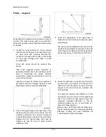
Forks should be inspected, at a minimum, every 12
months. If the truck is being used in a multi-shift or
heavy duty operation, they should be checked every
six months.
1.
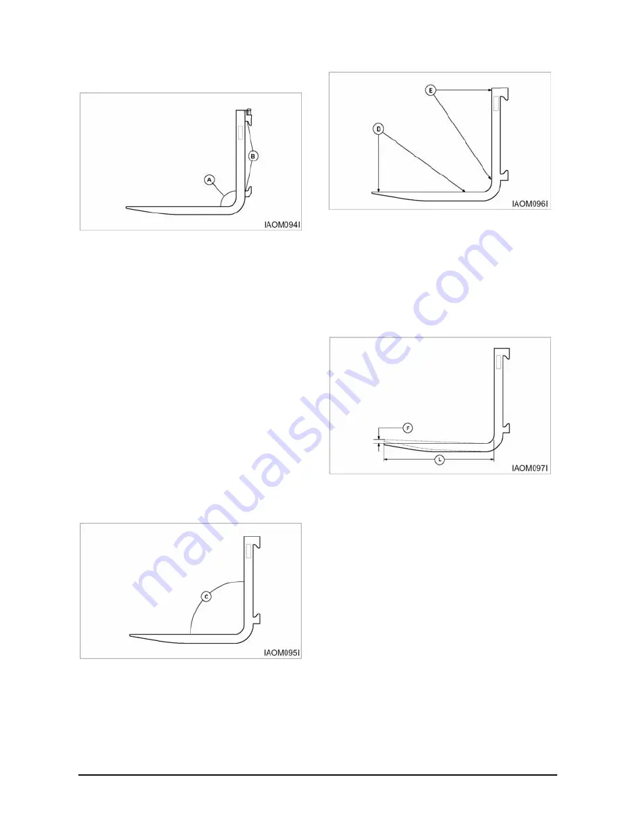
Inspect the forks carefully for cracks. Special
attention should be given to the heel section (A),
all weld areas and mounting brackets (B).
Inspect the top and bottom hooks on forks used
on hook type carriages and tubes on shaft
mounted forks.
Forks with cracks should be removed from
service.
"Wet Test" magnetic particle inspection is
generally preferred due to its sensitivity and the
ease of interpreting the results. Portable
equipment is usually recommended so it can be
moved to the lift truck.
Inspectors should be trained and qualified in
accordance with The American Society for Non
Destructive Testing, Level II Qualifications.
2.
Check the angle between the upper face of the
blade and the front face of the shank. The fork
should be withdrawn from service if angle (C)
exceeds 93 degrees or deviates by more than 3
degrees from an original angle other than 90
degrees, as may be found in some special
application forks.
3.
Check the straightness of the upper face of
blade (D) and the front face of shank (E) with a
straight edge.
The fork should be withdrawn from service if the
deviation from straightness exceeds 0.5 percent
of the length of the blade and/or the height of the
shank respectively 5 mm/1000 mm (0.18"/36").
4.
Check the difference in height of one fork tip to
the other when mounted on the fork carrier. A
difference in fork tip height can result in uneven
support of the load and cause problems with
entering loads.
The maximum recommended difference in fork
tip elevation (F) is 6.5 mm (0.25") for pallet forks
and 3 mm (0.125") for fully tapered forks. The
maximum allowable difference in fork tip
elevation between the two or more forks is 3
percent of blade length (L).
Replace one or both forks when the difference in
fork tip height exceeds the maximum allowable
difference. Contact your local DOOSAN Lift
Truck Dealer for further information.
Summary of Contents for D20G
Page 2: ......
Page 5: ...Specifications TORQUE SPECIFICATIONS SB2004E00 D e c 1 9 9 8 ...
Page 14: ......
Page 16: ......
Page 138: ...Diesel Engine Engine System 124 NOTE The crankshaft must rotate freely by hand 02900058 ...
Page 254: ......
Page 256: ......
Page 260: ......
Page 341: ...4TNV98 4TNE98 Diesel Engine Section 3 Engine 87 4TNE98 Engine Figure 6 1 ...
Page 423: ...4TNV98 4TNE98 Diesel Engine Section 4 Fuel System 169 Fuel System Components Figure 7 1 ...
Page 477: ...4TNV98 4TNE98 Diesel Engine Section 7 Starter Motor 223 Starter Motor Troubleshooting ...
Page 494: ...4TNV98 4TNE98 Diesel Engine Section 8 Troubleshooting 240 Troubleshooting Charts ...
Page 495: ...4TNV98 4TNE98 Diesel Engine Section 8 Troubleshooting 241 ...
Page 496: ...4TNV98 4TNE98 Diesel Engine Section 8 Troubleshooting 242 ...
Page 498: ...4TNV98 4TNE98 Diesel Engine Section 8 Troubleshooting 244 4TNE98 Engine ...
Page 499: ...Service Manual G424FE LP Engine G424F LP Gasoline Engine G20G G25G G30G SB4320E00 Jan 2008 ...
Page 500: ......
Page 502: ......
Page 529: ...G424F FE Service Manual Chapter 2 Recommended Maintenance 29 ...
Page 534: ...G424F FE Service Manual Chapter 3 Engine Mechanical System 34 MAIN BEARINGS 0 50 UNDERSIZE ...
Page 584: ...G424F FE Service Manual Chapter 3 Engine Mechanical System 84 ...
Page 729: ...G424F FE Service Manual 229 Chapter 8 Basic Troubleshooting ...
Page 731: ...G424F FE Service Manual 231 Chapter 8 Basic Troubleshooting ...
Page 806: ......
Page 808: ......
Page 810: ......
Page 820: ...Power Train System Operation 14 Hydraulic System ...
Page 822: ...Power Train System Operation 16 Hydraulic System ...
Page 824: ...Power Train System Operation 18 Hydraulic System ...
Page 826: ...Power Train System Operation 20 Hydraulic System ...
Page 856: ......
Page 858: ......
Page 860: ......
Page 930: ......
Page 932: ......
Page 934: ......
Page 936: ......
Page 1018: ......
Page 1023: ...A374081 01 ELECTRIC SCHEMATIC MODEL D20 25 30G EM0K2 EM0K3 Cummins B3 3 ...
Page 1024: ...A654030 00 ELECTRIC SCHEMATIC MODEL D20 25 30G EM0QM EM0QN Yanmar 4TNE98 Tier 3 ...
Page 1025: ...A604500 00 ELECTRIC SCHEMATIC MODEL G20 25 30G EM0QF EM0QG GM G424F Non Certi LP ...
Page 1026: ...A604510 00 ELECTRIC SCHEMATIC MODEL G20 25 30G EM0QH EM0QJ GM G424F Non Certi GAS ...
Page 1027: ...A604516 00 ELECTRIC SCHEMATIC MODEL G20 25 30G EM0QY EM0QZ GM G424FE Tier 3 LP ...
Page 1028: ......
Page 1030: ......
Page 1059: ...Safety Section 29 Lean away from the direction of fall Lean forward ...
Page 1071: ...General Section 41 Typical Example Side Shifter Serial Number If Equipped ...

