4TNV98 & 4TNE98 Diesel Engine
Section 3. Engine
126
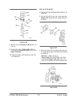
Figure 6-123
Inspection of Camshaft Bushing and Bores
1.
Measure the I.D. of the front bushing and the
remaining bores in the cylinder block. See
Camshaft on page 68 for specifications.
2.
If the camshaft bushing is not within specification,
replace it using the appropriate service tool. If the
remaining bores are not within specification, the
cylinder block will require replacement as there
are no bearing inserts used.
Inspection of Idler Gear and Shaft
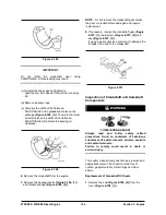
1.
Measure the outside diameter
(Figure 6-124, (1))
of the idler gear shaft
(Figure 6-124, (2))
. See
Idler Gear Shaft and Bushing on page 69 for
specifications.
2.
Measure the inside diameter
(Figure 6-124, (3))
of the idler gear bushing
(Figure 6-124, (4))
. See
Idler Gear Shaft and Bushing on page 69 for
specifications.
Figure 6-124
Honing and Boring
Pistons must move freely in the cylinders while
maintaining adequate compression and oil sealing.
If the cylinder walls are scuffed, scored, out-of-round,
or tapered beyond specifications, rebore and hone
to restore cylinders to usable condition. Slight
imperfections can be corrected by honing alone.
1. Boring
- Significant cylinder damage may be
corrected by boring the cylinder to an oversize
dimension. Refer to the appropriate parts catalog
for available oversize pistons and piston rings.
• Boring a cylinder should always be done in a
properly equipped machine shop.
• A bored cylinder should always be finished with a
hone to properly prepare the cylinder surface so
the new piston rings will seat properly.
• After the cylinder has been bored and honed,
install the appropriate oversize pistons and
piston rings.
2.
Honing
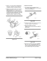
- Minor cylinder imperfections may be
corrected by using a rigid cylinder hone
(Figure 6-
126, (1))
. Be sure not to exceed the maximum
cylinder bore specification.
Deglazing
- A used cylinder that did not require
boring or honing, should always be deglazed with
a ball hone
(Figure 6-126, (2))
before installing
new piston rings. This will properly prepare the
cylinder surface to allow new piston rings to seat
properly.
NOTE
: When honing a cylinder, with either a ridged
hone or a ball hone
(Figure 6-125, (1))
, move the
rotating hone up and down in the cylinder bore to
accomplish a 30° to 40° crosshatch pattern
(Figure
6-125)
. This will provide the ideal surface for the
proper seating of new piston rings.
Summary of Contents for D20G
Page 2: ......
Page 5: ...Specifications TORQUE SPECIFICATIONS SB2004E00 D e c 1 9 9 8 ...
Page 14: ......
Page 16: ......
Page 138: ...Diesel Engine Engine System 124 NOTE The crankshaft must rotate freely by hand 02900058 ...
Page 254: ......
Page 256: ......
Page 260: ......
Page 341: ...4TNV98 4TNE98 Diesel Engine Section 3 Engine 87 4TNE98 Engine Figure 6 1 ...
Page 423: ...4TNV98 4TNE98 Diesel Engine Section 4 Fuel System 169 Fuel System Components Figure 7 1 ...
Page 477: ...4TNV98 4TNE98 Diesel Engine Section 7 Starter Motor 223 Starter Motor Troubleshooting ...
Page 494: ...4TNV98 4TNE98 Diesel Engine Section 8 Troubleshooting 240 Troubleshooting Charts ...
Page 495: ...4TNV98 4TNE98 Diesel Engine Section 8 Troubleshooting 241 ...
Page 496: ...4TNV98 4TNE98 Diesel Engine Section 8 Troubleshooting 242 ...
Page 498: ...4TNV98 4TNE98 Diesel Engine Section 8 Troubleshooting 244 4TNE98 Engine ...
Page 499: ...Service Manual G424FE LP Engine G424F LP Gasoline Engine G20G G25G G30G SB4320E00 Jan 2008 ...
Page 500: ......
Page 502: ......
Page 529: ...G424F FE Service Manual Chapter 2 Recommended Maintenance 29 ...
Page 534: ...G424F FE Service Manual Chapter 3 Engine Mechanical System 34 MAIN BEARINGS 0 50 UNDERSIZE ...
Page 584: ...G424F FE Service Manual Chapter 3 Engine Mechanical System 84 ...
Page 729: ...G424F FE Service Manual 229 Chapter 8 Basic Troubleshooting ...
Page 731: ...G424F FE Service Manual 231 Chapter 8 Basic Troubleshooting ...
Page 806: ......
Page 808: ......
Page 810: ......
Page 820: ...Power Train System Operation 14 Hydraulic System ...
Page 822: ...Power Train System Operation 16 Hydraulic System ...
Page 824: ...Power Train System Operation 18 Hydraulic System ...
Page 826: ...Power Train System Operation 20 Hydraulic System ...
Page 856: ......
Page 858: ......
Page 860: ......
Page 930: ......
Page 932: ......
Page 934: ......
Page 936: ......
Page 1018: ......
Page 1023: ...A374081 01 ELECTRIC SCHEMATIC MODEL D20 25 30G EM0K2 EM0K3 Cummins B3 3 ...
Page 1024: ...A654030 00 ELECTRIC SCHEMATIC MODEL D20 25 30G EM0QM EM0QN Yanmar 4TNE98 Tier 3 ...
Page 1025: ...A604500 00 ELECTRIC SCHEMATIC MODEL G20 25 30G EM0QF EM0QG GM G424F Non Certi LP ...
Page 1026: ...A604510 00 ELECTRIC SCHEMATIC MODEL G20 25 30G EM0QH EM0QJ GM G424F Non Certi GAS ...
Page 1027: ...A604516 00 ELECTRIC SCHEMATIC MODEL G20 25 30G EM0QY EM0QZ GM G424FE Tier 3 LP ...
Page 1028: ......
Page 1030: ......
Page 1059: ...Safety Section 29 Lean away from the direction of fall Lean forward ...
Page 1071: ...General Section 41 Typical Example Side Shifter Serial Number If Equipped ...


