G424F(FE) Service Manual
Index
5
AVV (Air Valve Vacuum) Testing.......... 184
Connection of the MI-07 Service Tool... 184
Idle Mixture Adjustment........................ 185
Parts Description......................................... 188
CA100 Mixer for G424FE Engine ......... 188
N-2007 Regulator for G424FE Engine.. 190
G424F LPG System Inspection and Repair..... 192
Removal and Installation............................. 192
G424F Fuel System Connections......... 193
Removal and Installation of N-2001 LP
Regulator/Converter............................. 194
Removal and Installation of CA100 Mixer
for G424F ............................................ 195
Tests and Adjustments................................ 197
N-2001 Regulator Service Testing........ 197
AVV (Air Valve Vacuum) Testing.......... 199
Connection of the MI-07 Service Tool... 199
Idle Mixture Adjustment........................ 200
G424F LP Fuel Systems with O2 Sensor
............................................................ 200
Parts Description......................................... 202
CA100 Mixer for G424F Engine............ 202
CA100 Disassembly and Service ......... 204
CA100 Disassembled Service .............. 205
N-2001 Regulator for G424F Engine .... 206
N2001 Regulator Disassembly Steps: .. 208
N2001 Disassembled Service .............. 210
Chapter 7. MPI GASOLINE FUEL
DELIVERY SYSTEM
Specification .................................................... 211
Components Location ..................................... 212
Fuel Pressure Test........................................... 213
Release The Internal Pressure.................... 213
Install Service Tool For Measuring The Fuel
Pressure ..................................................... 213
Inspect Fuel Leakage On Connection.......... 214
Fuel Pressure Test...................................... 214
Release The Internal Pressure.................... 214
Remove Service Tool And Connect the Fuel
Line ............................................................ 215
Inspect Fuel Leakage On Connection.......... 215
Injector ............................................................. 215
Component Location................................... 215
Description.................................................. 215
Specification ............................................... 215
Schematic diagram ..................................... 215
Injector Inspection....................................... 216
Resistance Measurement Between Terminals
....................................................................216
Removal......................................................216
Inspection....................................................217
Installation ...................................................217
Fuel Pump.........................................................218
Removal (Including Fuel Filter And Fuel
Pressure Regulator).....................................218
Chapter 8. BASIC TROUBLESHOOTING
Preliminary Checks ..........................................219
Before Starting ............................................219
Visual/Physical check ..................................219
Basic Troubleshooting Guide ..........................220
Customer Problem Analysis Sheet...............220
Basic Inspection Procedure .........................221
Connector Inspection Procedure..................222
Symptom Troubleshooting Guide Chart for MPI
Gasoline System .........................................226
Basic Troubleshooting .....................................232
Intermittents.................................................232
Corrective Action .........................................232
Surges and/or Stumbles ..............................233
Engine Cranking but Will Not Start / Difficult to
Start ............................................................234
Engine Cranking but Will Not Start / Difficult to
Start (cont’d.)...............................................235
Lack of Power, Slow to Respond / Poor High
Speed Performance / Hesitation During
Acceleration.................................................236
Lack of Power, Slow to Respond / Poor High
Speed Performance / Hesitation During
Acceleration (cont’d.) ...................................237
Detonation / Spark Knock ............................238
Backfire .......................................................239
Dieseling, Run-on ........................................239
Rough, Unstable, Incorrect Idle, or Stalling ..240
Rough, Unstable, Incorrect Idle, or Stalling
(cont’d.) .......................................................241
Cuts Out, Misses .........................................242
Poor Fuel Economy / Excessive Fuel
Consumption LPG Exhaust Smell ................243
High Idle Speed...........................................244
Excessive Exhaust Emissions or Odors .......245
Diagnostic Aids for Rich / Lean Operation....246
Chart T-1 Restricted Exhaust System Check ....247
Summary of Contents for D20G
Page 2: ......
Page 5: ...Specifications TORQUE SPECIFICATIONS SB2004E00 D e c 1 9 9 8 ...
Page 14: ......
Page 16: ......
Page 138: ...Diesel Engine Engine System 124 NOTE The crankshaft must rotate freely by hand 02900058 ...
Page 254: ......
Page 256: ......
Page 260: ......
Page 341: ...4TNV98 4TNE98 Diesel Engine Section 3 Engine 87 4TNE98 Engine Figure 6 1 ...
Page 423: ...4TNV98 4TNE98 Diesel Engine Section 4 Fuel System 169 Fuel System Components Figure 7 1 ...
Page 477: ...4TNV98 4TNE98 Diesel Engine Section 7 Starter Motor 223 Starter Motor Troubleshooting ...
Page 494: ...4TNV98 4TNE98 Diesel Engine Section 8 Troubleshooting 240 Troubleshooting Charts ...
Page 495: ...4TNV98 4TNE98 Diesel Engine Section 8 Troubleshooting 241 ...
Page 496: ...4TNV98 4TNE98 Diesel Engine Section 8 Troubleshooting 242 ...
Page 498: ...4TNV98 4TNE98 Diesel Engine Section 8 Troubleshooting 244 4TNE98 Engine ...
Page 499: ...Service Manual G424FE LP Engine G424F LP Gasoline Engine G20G G25G G30G SB4320E00 Jan 2008 ...
Page 500: ......
Page 502: ......
Page 529: ...G424F FE Service Manual Chapter 2 Recommended Maintenance 29 ...
Page 534: ...G424F FE Service Manual Chapter 3 Engine Mechanical System 34 MAIN BEARINGS 0 50 UNDERSIZE ...
Page 584: ...G424F FE Service Manual Chapter 3 Engine Mechanical System 84 ...
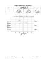
Page 729: ...G424F FE Service Manual 229 Chapter 8 Basic Troubleshooting ...
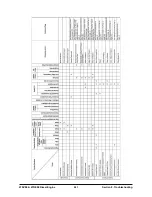
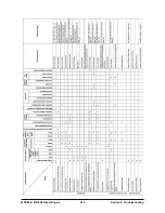
Page 731: ...G424F FE Service Manual 231 Chapter 8 Basic Troubleshooting ...
Page 806: ......
Page 808: ......
Page 810: ......
Page 820: ...Power Train System Operation 14 Hydraulic System ...
Page 822: ...Power Train System Operation 16 Hydraulic System ...
Page 824: ...Power Train System Operation 18 Hydraulic System ...
Page 826: ...Power Train System Operation 20 Hydraulic System ...
Page 856: ......
Page 858: ......
Page 860: ......
Page 930: ......
Page 932: ......
Page 934: ......
Page 936: ......
Page 1018: ......
Page 1023: ...A374081 01 ELECTRIC SCHEMATIC MODEL D20 25 30G EM0K2 EM0K3 Cummins B3 3 ...
Page 1024: ...A654030 00 ELECTRIC SCHEMATIC MODEL D20 25 30G EM0QM EM0QN Yanmar 4TNE98 Tier 3 ...
Page 1025: ...A604500 00 ELECTRIC SCHEMATIC MODEL G20 25 30G EM0QF EM0QG GM G424F Non Certi LP ...
Page 1026: ...A604510 00 ELECTRIC SCHEMATIC MODEL G20 25 30G EM0QH EM0QJ GM G424F Non Certi GAS ...
Page 1027: ...A604516 00 ELECTRIC SCHEMATIC MODEL G20 25 30G EM0QY EM0QZ GM G424FE Tier 3 LP ...
Page 1028: ......
Page 1030: ......
Page 1059: ...Safety Section 29 Lean away from the direction of fall Lean forward ...
Page 1071: ...General Section 41 Typical Example Side Shifter Serial Number If Equipped ...

