G424F(FE) Service Manual
Chapter 2. Recommended Maintenance
20
Cooling System Maintenance
Coolant Recommendation
The engine cooling system is provided with a
mixture of 50% ethylene glycol anti-freeze and 50%
water (For the vehicles of tropical area, the engine
cooling system is provided with a mixture of 40%
ethylene glycol anti-freeze and 60% water at the
time of manufacture.)
Since the cylinder head and water pump body are
made of aluminum alloy casting, be sure to use a 30
to 60% ethylene glycol antifreeze coolant to assure
corrosion protection and freezing prevention.
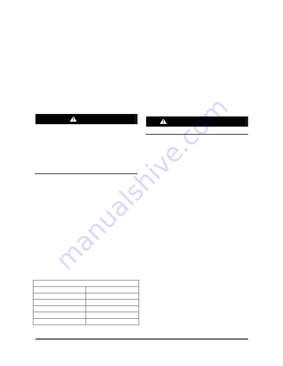
CAUTION
If the concentration of the antifreeze is below
30%, the anticorrosion property will be adversely
affected. In addition, if the concentration is
above 60%, both the antifreeze and engine
cooling properties will decrease, adversely
affecting the engine. For these reasons, be sure
to maintain the concentration level within the
specified range.
Coolant Water
Hard water, or water with high levels of calcium and
magnesium ions, encourages the formation of
insoluble chemical compounds by combining with
cooling system additives such as silicates and
phosphates.
The tendency of silicates and phosphates to
precipitate out-of-solution increases with increasing
water hardness. Hard water, or water with high
levels of calcium and magnesium ions encourages
the formation of insoluble chemicals, especially after
a number of heating and cooling cycles.
DOOSAN prefers the use of distilled water or
deionized water to reduce the potential and severity
of chemical insolubility.
Acceptable Water
Water Content
Limits (ppm)
Chlorides (CI)
40 maximum
Sulfates (SO4)
50 maximum
Total Hardness
80mg/
ℓ
maximum
Total Solids
250 maximum
pH
6.0 ~ 8.0
ppm = parts per million
Antifreeze
DOOSAN recommends selecting automotive
antifreeze suitable for gasoline engines using
aluminum alloy parts. The antifreeze should meet
ASTM-D3306 standard.
Check Coolant Level
•
The items below are a general guideline for
system checks. Refer to the engine
manufacturer’s specific recommendations for
proper procedures.
•
Engine must be off and cold.
WARNING—PROPER USE
Never remove the pressure cap on a hot engine.
•
The coolant level should be equal to the “COLD”
mark on the coolant recovery tank.
•
Add approve coolant to the specified level if the
system is low.
Inspect Coolant Hoses
•
Visually inspect coolant hoses and clamps.
Remember to check the two coolant lines that
connect to the pressure regulator/converter.
•
Replace any hose that shows signs of leakage,
swelling, cracking, abrasion or deterioration.
Summary of Contents for D20G
Page 2: ......
Page 5: ...Specifications TORQUE SPECIFICATIONS SB2004E00 D e c 1 9 9 8 ...
Page 14: ......
Page 16: ......
Page 138: ...Diesel Engine Engine System 124 NOTE The crankshaft must rotate freely by hand 02900058 ...
Page 254: ......
Page 256: ......
Page 260: ......
Page 341: ...4TNV98 4TNE98 Diesel Engine Section 3 Engine 87 4TNE98 Engine Figure 6 1 ...
Page 423: ...4TNV98 4TNE98 Diesel Engine Section 4 Fuel System 169 Fuel System Components Figure 7 1 ...
Page 477: ...4TNV98 4TNE98 Diesel Engine Section 7 Starter Motor 223 Starter Motor Troubleshooting ...
Page 494: ...4TNV98 4TNE98 Diesel Engine Section 8 Troubleshooting 240 Troubleshooting Charts ...
Page 495: ...4TNV98 4TNE98 Diesel Engine Section 8 Troubleshooting 241 ...
Page 496: ...4TNV98 4TNE98 Diesel Engine Section 8 Troubleshooting 242 ...
Page 498: ...4TNV98 4TNE98 Diesel Engine Section 8 Troubleshooting 244 4TNE98 Engine ...
Page 499: ...Service Manual G424FE LP Engine G424F LP Gasoline Engine G20G G25G G30G SB4320E00 Jan 2008 ...
Page 500: ......
Page 502: ......
Page 529: ...G424F FE Service Manual Chapter 2 Recommended Maintenance 29 ...
Page 534: ...G424F FE Service Manual Chapter 3 Engine Mechanical System 34 MAIN BEARINGS 0 50 UNDERSIZE ...
Page 584: ...G424F FE Service Manual Chapter 3 Engine Mechanical System 84 ...
Page 729: ...G424F FE Service Manual 229 Chapter 8 Basic Troubleshooting ...
Page 731: ...G424F FE Service Manual 231 Chapter 8 Basic Troubleshooting ...
Page 806: ......
Page 808: ......
Page 810: ......
Page 820: ...Power Train System Operation 14 Hydraulic System ...
Page 822: ...Power Train System Operation 16 Hydraulic System ...
Page 824: ...Power Train System Operation 18 Hydraulic System ...
Page 826: ...Power Train System Operation 20 Hydraulic System ...
Page 856: ......
Page 858: ......
Page 860: ......
Page 930: ......
Page 932: ......
Page 934: ......
Page 936: ......
Page 1018: ......
Page 1023: ...A374081 01 ELECTRIC SCHEMATIC MODEL D20 25 30G EM0K2 EM0K3 Cummins B3 3 ...
Page 1024: ...A654030 00 ELECTRIC SCHEMATIC MODEL D20 25 30G EM0QM EM0QN Yanmar 4TNE98 Tier 3 ...
Page 1025: ...A604500 00 ELECTRIC SCHEMATIC MODEL G20 25 30G EM0QF EM0QG GM G424F Non Certi LP ...
Page 1026: ...A604510 00 ELECTRIC SCHEMATIC MODEL G20 25 30G EM0QH EM0QJ GM G424F Non Certi GAS ...
Page 1027: ...A604516 00 ELECTRIC SCHEMATIC MODEL G20 25 30G EM0QY EM0QZ GM G424FE Tier 3 LP ...
Page 1028: ......
Page 1030: ......
Page 1059: ...Safety Section 29 Lean away from the direction of fall Lean forward ...
Page 1071: ...General Section 41 Typical Example Side Shifter Serial Number If Equipped ...


