G424F(FE) Service Manual
Chapter 3. Engine Mechanical System
62
Testing and Adjusting
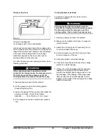
Adhere to the following warnings when performing
any tests or adjustments while the engine is running:
WARNING
Work carefully around an engine that is running.
Engine parts that are hot, or parts that are
moving, can cause personal injury.
WARNING
Exhaust fumes contain carbon monoxide (CO)
which can cause personal injury or death. Start
and operate the engine in a well ventilated area
only. In an enclosed area, vent the exhaust to
the outside.
This engine has a pressure type cooling system. A
pressure type cooling system gives two advantages.
The first advantage is that the cooling system can
have safe operation at a temperature that is higher
than the normal boiling (steam) point of water. The
second advantage is that this type system prevents
cavitation (the sudden making of low pressure
bubbles in liquids by mechanical forces ) in the
water pump. With this type system, it is more difficult
for an air or steam pocket to be made in the cooling
system.
The cause for an engine getting too hot is generally
because regular inspections of the cooling system
were not made. Make a visual inspection of the
cooling system before testing with testing equipment.
Cooling System Visual Inspection
WARNING
Do not loosen the filler cap or pressure cap on a
hot engine. Steam or hot coolant can cause
severe burns.
1.
After the engine is cool, loosen the filler cap (on a
radiator with a pressure cap, turn it to the first
stop) to let pressure out of the cooling system.
Then remove filler or pressure cap.
2.
Check coolant level in the cooling system.
3.
Look for leaks in the system.
4.
Look for bent radiator fins. Be sure that air flow
through the radiator does not have a restriction.
5.
Inspect the drive belts for the fan.
6.
Check for damage to the fan blades.
7.
Look for air or combustion gas in the cooling
system.
8.
Inspect the filler cap and the surface that seals
the cap. This surface must be clean.
9.
Look for a large amount of dirt in the radiator core
and on the engine.
10.
Check for loose or missing fan shrouds that
cause poor flow of cooling air.
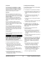
Cooling System Tests
Remember that temperature and pressure work
together. When making a diagnosis of a cooling
system problem, temperature and pressure must
both be checked. Cooling system pressure will have
an effect on cooling system temperatures. For an
example, look at the chart to see the effect of
pressure and height above sea level on the boiling
(steam) point of water.
Summary of Contents for D20G
Page 2: ......
Page 5: ...Specifications TORQUE SPECIFICATIONS SB2004E00 D e c 1 9 9 8 ...
Page 14: ......
Page 16: ......
Page 138: ...Diesel Engine Engine System 124 NOTE The crankshaft must rotate freely by hand 02900058 ...
Page 254: ......
Page 256: ......
Page 260: ......
Page 341: ...4TNV98 4TNE98 Diesel Engine Section 3 Engine 87 4TNE98 Engine Figure 6 1 ...
Page 423: ...4TNV98 4TNE98 Diesel Engine Section 4 Fuel System 169 Fuel System Components Figure 7 1 ...
Page 477: ...4TNV98 4TNE98 Diesel Engine Section 7 Starter Motor 223 Starter Motor Troubleshooting ...
Page 494: ...4TNV98 4TNE98 Diesel Engine Section 8 Troubleshooting 240 Troubleshooting Charts ...
Page 495: ...4TNV98 4TNE98 Diesel Engine Section 8 Troubleshooting 241 ...
Page 496: ...4TNV98 4TNE98 Diesel Engine Section 8 Troubleshooting 242 ...
Page 498: ...4TNV98 4TNE98 Diesel Engine Section 8 Troubleshooting 244 4TNE98 Engine ...
Page 499: ...Service Manual G424FE LP Engine G424F LP Gasoline Engine G20G G25G G30G SB4320E00 Jan 2008 ...
Page 500: ......
Page 502: ......
Page 529: ...G424F FE Service Manual Chapter 2 Recommended Maintenance 29 ...
Page 534: ...G424F FE Service Manual Chapter 3 Engine Mechanical System 34 MAIN BEARINGS 0 50 UNDERSIZE ...
Page 584: ...G424F FE Service Manual Chapter 3 Engine Mechanical System 84 ...
Page 729: ...G424F FE Service Manual 229 Chapter 8 Basic Troubleshooting ...
Page 731: ...G424F FE Service Manual 231 Chapter 8 Basic Troubleshooting ...
Page 806: ......
Page 808: ......
Page 810: ......
Page 820: ...Power Train System Operation 14 Hydraulic System ...
Page 822: ...Power Train System Operation 16 Hydraulic System ...
Page 824: ...Power Train System Operation 18 Hydraulic System ...
Page 826: ...Power Train System Operation 20 Hydraulic System ...
Page 856: ......
Page 858: ......
Page 860: ......
Page 930: ......
Page 932: ......
Page 934: ......
Page 936: ......
Page 1018: ......
Page 1023: ...A374081 01 ELECTRIC SCHEMATIC MODEL D20 25 30G EM0K2 EM0K3 Cummins B3 3 ...
Page 1024: ...A654030 00 ELECTRIC SCHEMATIC MODEL D20 25 30G EM0QM EM0QN Yanmar 4TNE98 Tier 3 ...
Page 1025: ...A604500 00 ELECTRIC SCHEMATIC MODEL G20 25 30G EM0QF EM0QG GM G424F Non Certi LP ...
Page 1026: ...A604510 00 ELECTRIC SCHEMATIC MODEL G20 25 30G EM0QH EM0QJ GM G424F Non Certi GAS ...
Page 1027: ...A604516 00 ELECTRIC SCHEMATIC MODEL G20 25 30G EM0QY EM0QZ GM G424FE Tier 3 LP ...
Page 1028: ......
Page 1030: ......
Page 1059: ...Safety Section 29 Lean away from the direction of fall Lean forward ...
Page 1071: ...General Section 41 Typical Example Side Shifter Serial Number If Equipped ...


