G424F(FE) Service Manual
Chapter 5. Engine Management System (EMS)
135
pressure regulator outlet pressure changes by the
same amount and in the same direction. The end
result is that a change in FTV modulation changes
the outlet pressure of the regulator/fuel inlet
pressure of the mixer, and thus the AFR. A major
benefit of this trim system results from the use of
mixer inlet pressure and AVV as the reference
pressure extremes. The pressure differential across
the mixer fuel valve is related to these same two
pressures, and thus so is fuel flow. Given this
arrangement, the bias pressure delta scales with the
fuel cone delta pressure. The result is that the trim
system control authority and resolution on AFR
stays relatively constant for the entire speed and
load range of the engine.
SECM
The Small Engine Control Module (SECM) controls
the LPG lock-off solenoid valve and the FTVs. The
lock-off solenoid is energized when fueling with LPG
and the engine is turning. FTV modulation frequency
will be varied as a function of rpm by the SECM in
order to avoid resonance phenomena in the fuel
system. FTV commands will be altered by the
SECM in order to maintain a stoichiometric air-fuel
ratio. Commands are based primarily on feedback
from the exhaust gas oxygen sensor, with an offset
for fuel temperature.
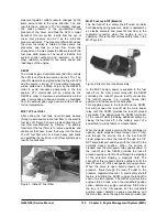
MI-07 LP Fuel Filter
After exiting the fuel tank, liquid propane passes
through a serviceable inline fuel filter to the electric
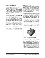
fuel lock off. Figure 3 shows a typical inline type LP
fuel filter manufactured by Century. The primary
function of the fuel filter is to remove particles and
sediments that have found their way into the tank.
The LP fuel filter will not remove heavy end solids
and paraffins that build up in LPG fuel systems as a
result of vaporization.
Figure 3. Inline LP Fuel Filter
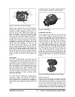
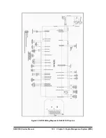
MI-07 Fuel Lock-Off (Electric)
The fuel lock-off is a safety shutoff valve, normally
held closed by spring pressure, which is operated by
an electric solenoid and prevents fuel flow to the
regulator/ converter when the engine is not in
operation. This is the first of three safety locks in the
MI-07 system.
Figure 4. Electric Fuel Lock Assembly
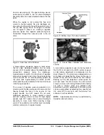
In the MI-07 design, power is supplied to the fuel
lock-off via the main power relay with the SECM
controlling the lock-off ground (earth) connection.
The lock-off remains in a normally closed (NC)
position until the key switch is activated.
This supplies power to the lock-off and the SECM,
but will not open the lock-off via the main power
relay until the SECM provides the lock-off ground
connection. This design gives the SECM full control
of the lock-off while providing additional safety by
closing the fuel lock-off in the unlikely event of a
power failure, wiring failure or module failure.
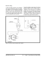
When the liquid service valve in the fuel container is
opened, liquid propane flows through the LP filter
and through the service line to the fuel lock-off.
Liquid propane enters the lock-off through the 1/4”
NPT liquid inlet port and stops with the lock-off in the
normally closed position. When the engine is
cranked over the main power relay applies power to
the lock-off and the SECM provides the lock-off
ground causing current to flow through the windings
of the solenoid creating a magnetic field. The
strength of this magnetic field is sufficient to lift the
lock-off valve off of its seat against spring pressure.
When the valve is open liquid propane, at tank
pressure, flows through the lock-off outlet to the
pressure regulator/converter. A stall safety shutoff
feature is built into the SECM to close the lock-off in
case of a stall condition. The SECM monitors three
engine states: Crank, when the crankshaft position
sensor detects any engine revolutions; Stall, when
the key is in the ON position but the crankshaft
position sensor detects no engine revolutions; and
the Run state, when the engine reaches pre-idle rpm.
Summary of Contents for D20G
Page 2: ......
Page 5: ...Specifications TORQUE SPECIFICATIONS SB2004E00 D e c 1 9 9 8 ...
Page 14: ......
Page 16: ......
Page 138: ...Diesel Engine Engine System 124 NOTE The crankshaft must rotate freely by hand 02900058 ...
Page 254: ......
Page 256: ......
Page 260: ......
Page 341: ...4TNV98 4TNE98 Diesel Engine Section 3 Engine 87 4TNE98 Engine Figure 6 1 ...
Page 423: ...4TNV98 4TNE98 Diesel Engine Section 4 Fuel System 169 Fuel System Components Figure 7 1 ...
Page 477: ...4TNV98 4TNE98 Diesel Engine Section 7 Starter Motor 223 Starter Motor Troubleshooting ...
Page 494: ...4TNV98 4TNE98 Diesel Engine Section 8 Troubleshooting 240 Troubleshooting Charts ...
Page 495: ...4TNV98 4TNE98 Diesel Engine Section 8 Troubleshooting 241 ...
Page 496: ...4TNV98 4TNE98 Diesel Engine Section 8 Troubleshooting 242 ...
Page 498: ...4TNV98 4TNE98 Diesel Engine Section 8 Troubleshooting 244 4TNE98 Engine ...
Page 499: ...Service Manual G424FE LP Engine G424F LP Gasoline Engine G20G G25G G30G SB4320E00 Jan 2008 ...
Page 500: ......
Page 502: ......
Page 529: ...G424F FE Service Manual Chapter 2 Recommended Maintenance 29 ...
Page 534: ...G424F FE Service Manual Chapter 3 Engine Mechanical System 34 MAIN BEARINGS 0 50 UNDERSIZE ...
Page 584: ...G424F FE Service Manual Chapter 3 Engine Mechanical System 84 ...
Page 729: ...G424F FE Service Manual 229 Chapter 8 Basic Troubleshooting ...
Page 731: ...G424F FE Service Manual 231 Chapter 8 Basic Troubleshooting ...
Page 806: ......
Page 808: ......
Page 810: ......
Page 820: ...Power Train System Operation 14 Hydraulic System ...
Page 822: ...Power Train System Operation 16 Hydraulic System ...
Page 824: ...Power Train System Operation 18 Hydraulic System ...
Page 826: ...Power Train System Operation 20 Hydraulic System ...
Page 856: ......
Page 858: ......
Page 860: ......
Page 930: ......
Page 932: ......
Page 934: ......
Page 936: ......
Page 1018: ......
Page 1023: ...A374081 01 ELECTRIC SCHEMATIC MODEL D20 25 30G EM0K2 EM0K3 Cummins B3 3 ...
Page 1024: ...A654030 00 ELECTRIC SCHEMATIC MODEL D20 25 30G EM0QM EM0QN Yanmar 4TNE98 Tier 3 ...
Page 1025: ...A604500 00 ELECTRIC SCHEMATIC MODEL G20 25 30G EM0QF EM0QG GM G424F Non Certi LP ...
Page 1026: ...A604510 00 ELECTRIC SCHEMATIC MODEL G20 25 30G EM0QH EM0QJ GM G424F Non Certi GAS ...
Page 1027: ...A604516 00 ELECTRIC SCHEMATIC MODEL G20 25 30G EM0QY EM0QZ GM G424FE Tier 3 LP ...
Page 1028: ......
Page 1030: ......
Page 1059: ...Safety Section 29 Lean away from the direction of fall Lean forward ...
Page 1071: ...General Section 41 Typical Example Side Shifter Serial Number If Equipped ...


