G424F(FE) Service Manual
Chapter 5. Engine Management System (EMS)
155
imbalance on the secondary diaphragm, which
overcomes the secondary spring force, opening the
secondary valve and allowing vapor propane to flow
out of the expansion chamber, through the
secondary chamber to the mixer.
Because vapor propane has now left the expansion
chamber, the pressure in the chamber will drop,
causing the primary diaphragm spring force to re-
open the primary valve allowing liquid propane to
enter the regulator, and the entire process starts
again. This creates a balanced condition between
the primary and secondary chambers allowing for a
constant flow of fuel to the mixer as long as the
demand from the engine is present. The fuel flow is
maintained at a constant output pressure, due to the
calibrated secondary spring. The amount of fuel
flowing will vary depending on how far the
secondary valve opens in response to the negative
pressure signal generated by the air/fuel mixer. The
strength of that negative pressure signal developed
by the mixer is directly related to the amount of air
flowing through the mixer into the engine. With this
process, the larger the quantity of air flowing into the
engine, the larger the amount of fuel flowing to the
mixer.
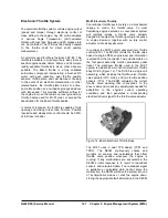
CA100 Mixer
The mixer is installed above the throttle body and
meters gaseous fuel into the airstream at a rate that
is proportional to the volumetric flow rate of air. The
ratio between volumetric airflow and volumetric fuel
flow is controlled by the shaping of the mixer fuel
cone and biased by the controllable fuel supply
pressure delivered by the pressure regulator. Fuel
flow must be metered accurately over the full range
of airflows. Pressure drop across the mixer air valve
must be minimized to assure maximum power
output from the engine.
A higher flow mixer is required on larger engines. A
lower flow mixer is required on smaller engines.
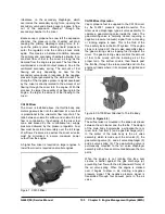
Figure 7. CA100 Mixer
CA100 Mixer Operation
Vapor propane fuel is supplied to the CA100 mixer
by the N-2001 pressure regulator/converter. The
mixer uses a diaphragm type air valve assembly to
operate a gas-metering valve inside the mixer. The
gas-metering valve is normally closed, requiring a
negative pressure (vacuum) signal from a cranking
or running engine to open. This is the third of the
three safety locks in the MI-07 system. If the engine
stops or is turned off, the air valve assembly closes
the gas-metering valve, stopping fuel flow past the
mixer. The gas-metering valve controls the amount
of fuel to be mixed with the incoming air at the
proper ratio. The air/fuel mixture then travels past
the throttle, through the intake manifold and into the
engine cylinders where it is compressed, ignited and
burned.
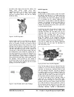
Figure 8. CA100 Mixer Attached to Throttle Body
(Refer
to Figure 98
.)
The air/fuel mixer is mounted in the intake air stream
between the air cleaner and the throttle. The design
of the main body incorporates a cylindrical bore or
mixer bore, fuel inlet (1) and a gas discharge jet (2).
In the center of the main body is the air valve
assembly, which is made up of the air valve (3), the
gas-metering valve (4), and air valve diaphragm (5)
and air valve spring (6). The gas-metering valve is
permanently mounted to the air valve diaphragm
assembly with a face seal mounted between the two
parts.
When the engine is not running this face seal
creates a barrier against the gas discharge jet,
preventing fuel flow with the aid (downward force) of
the air valve spring. When the engine is cranked
over it begins to draw in air, creating a negative
pressure signal. This negative pressure signal is
transmitted through four vacuum ports in the air
valve.
Summary of Contents for D20G
Page 2: ......
Page 5: ...Specifications TORQUE SPECIFICATIONS SB2004E00 D e c 1 9 9 8 ...
Page 14: ......
Page 16: ......
Page 138: ...Diesel Engine Engine System 124 NOTE The crankshaft must rotate freely by hand 02900058 ...
Page 254: ......
Page 256: ......
Page 260: ......
Page 341: ...4TNV98 4TNE98 Diesel Engine Section 3 Engine 87 4TNE98 Engine Figure 6 1 ...
Page 423: ...4TNV98 4TNE98 Diesel Engine Section 4 Fuel System 169 Fuel System Components Figure 7 1 ...
Page 477: ...4TNV98 4TNE98 Diesel Engine Section 7 Starter Motor 223 Starter Motor Troubleshooting ...
Page 494: ...4TNV98 4TNE98 Diesel Engine Section 8 Troubleshooting 240 Troubleshooting Charts ...
Page 495: ...4TNV98 4TNE98 Diesel Engine Section 8 Troubleshooting 241 ...
Page 496: ...4TNV98 4TNE98 Diesel Engine Section 8 Troubleshooting 242 ...
Page 498: ...4TNV98 4TNE98 Diesel Engine Section 8 Troubleshooting 244 4TNE98 Engine ...
Page 499: ...Service Manual G424FE LP Engine G424F LP Gasoline Engine G20G G25G G30G SB4320E00 Jan 2008 ...
Page 500: ......
Page 502: ......
Page 529: ...G424F FE Service Manual Chapter 2 Recommended Maintenance 29 ...
Page 534: ...G424F FE Service Manual Chapter 3 Engine Mechanical System 34 MAIN BEARINGS 0 50 UNDERSIZE ...
Page 584: ...G424F FE Service Manual Chapter 3 Engine Mechanical System 84 ...
Page 729: ...G424F FE Service Manual 229 Chapter 8 Basic Troubleshooting ...
Page 731: ...G424F FE Service Manual 231 Chapter 8 Basic Troubleshooting ...
Page 806: ......
Page 808: ......
Page 810: ......
Page 820: ...Power Train System Operation 14 Hydraulic System ...
Page 822: ...Power Train System Operation 16 Hydraulic System ...
Page 824: ...Power Train System Operation 18 Hydraulic System ...
Page 826: ...Power Train System Operation 20 Hydraulic System ...
Page 856: ......
Page 858: ......
Page 860: ......
Page 930: ......
Page 932: ......
Page 934: ......
Page 936: ......
Page 1018: ......
Page 1023: ...A374081 01 ELECTRIC SCHEMATIC MODEL D20 25 30G EM0K2 EM0K3 Cummins B3 3 ...
Page 1024: ...A654030 00 ELECTRIC SCHEMATIC MODEL D20 25 30G EM0QM EM0QN Yanmar 4TNE98 Tier 3 ...
Page 1025: ...A604500 00 ELECTRIC SCHEMATIC MODEL G20 25 30G EM0QF EM0QG GM G424F Non Certi LP ...
Page 1026: ...A604510 00 ELECTRIC SCHEMATIC MODEL G20 25 30G EM0QH EM0QJ GM G424F Non Certi GAS ...
Page 1027: ...A604516 00 ELECTRIC SCHEMATIC MODEL G20 25 30G EM0QY EM0QZ GM G424FE Tier 3 LP ...
Page 1028: ......
Page 1030: ......
Page 1059: ...Safety Section 29 Lean away from the direction of fall Lean forward ...
Page 1071: ...General Section 41 Typical Example Side Shifter Serial Number If Equipped ...

