G424F(FE) Service Manual
Chapter 6. LPG FUEL DELIVERY SYSTEM
197
Tests and Adjustments
WARNING – PROPER USE
•
LP gas is highly flammable. To prevent perso-
nal injury, keep fire and flammable materials
away from the lift truck when work is done on
the fuel system.
•
Gas vapor may reduce oxygen available for
breathing, cause headache, nausea, dizziness
and unconsciousness and lead to injury or
death. Always operate the forklift in a well
ventilated area
•
Liquid propane may cause freezing of tissue or
frostbite. Avoid direct contact with skin or
tissue; always wear appropriate safety
protection including gloves and safety glasses
when working with liquid propane.
N-2001 Regulator Service Testing
For checking the N-2001 regulator/converter
operation, the following tests can be performed. To
check the secondary regulation (output) a simple
vacuum hand pump can be used to simulate the
vacuum signal transmitted from the air/fuel mixer
when the engine is running. See listing below for
required hardware.
Break-Off Test
Secondary Stage Test Hardware
1.
Hand vacuum pump
2.
Regulator vapor outlet test fitting 3/4” NPT x 1/4”
hose barb
3.
Union Tee 1/4” NPT with three 1/4” NPT x 1/4”
hose barb
4.
Vacuum hose
5.
0-3” WC Magnehelic gauge (inches of water
column)
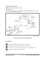
Secondary Stage (Break-Off) Test
1.
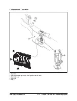
Connect the vacuum pump, the Magnehelic
gauge and the regulator vapor outlet to the Union
Tee fitting (Figure 30). Make sure there is no
leakage at any of the fittings.
2.
Using the vacuum pump slowly apply enough
vacuum to measure above -2” WC on the gauge.
This vacuum signal opens the secondary valve in
the N-2001 regulator/converter.
3.
Release the vacuum pump lever and you will see
the gauge needle start falling back toward zero.
When the pressure drops just below the specified
break-off pressure (-1.2 “ WC) of the secondary
spring, the needle should stop moving.
4.
At this point the secondary valve should close. If
the secondary valve seat or the secondary
diaphragm is leaking the gauge needle will
continue to fall toward zero (proportional to the
leak size). An excessively rich air/fuel mixture can
be caused by a secondary valve seat leak and the
regulator should be replaced.
Figure 30. Secondary Stage Test Connection
Summary of Contents for D20G
Page 2: ......
Page 5: ...Specifications TORQUE SPECIFICATIONS SB2004E00 D e c 1 9 9 8 ...
Page 14: ......
Page 16: ......
Page 138: ...Diesel Engine Engine System 124 NOTE The crankshaft must rotate freely by hand 02900058 ...
Page 254: ......
Page 256: ......
Page 260: ......
Page 341: ...4TNV98 4TNE98 Diesel Engine Section 3 Engine 87 4TNE98 Engine Figure 6 1 ...
Page 423: ...4TNV98 4TNE98 Diesel Engine Section 4 Fuel System 169 Fuel System Components Figure 7 1 ...
Page 477: ...4TNV98 4TNE98 Diesel Engine Section 7 Starter Motor 223 Starter Motor Troubleshooting ...
Page 494: ...4TNV98 4TNE98 Diesel Engine Section 8 Troubleshooting 240 Troubleshooting Charts ...
Page 495: ...4TNV98 4TNE98 Diesel Engine Section 8 Troubleshooting 241 ...
Page 496: ...4TNV98 4TNE98 Diesel Engine Section 8 Troubleshooting 242 ...
Page 498: ...4TNV98 4TNE98 Diesel Engine Section 8 Troubleshooting 244 4TNE98 Engine ...
Page 499: ...Service Manual G424FE LP Engine G424F LP Gasoline Engine G20G G25G G30G SB4320E00 Jan 2008 ...
Page 500: ......
Page 502: ......
Page 529: ...G424F FE Service Manual Chapter 2 Recommended Maintenance 29 ...
Page 534: ...G424F FE Service Manual Chapter 3 Engine Mechanical System 34 MAIN BEARINGS 0 50 UNDERSIZE ...
Page 584: ...G424F FE Service Manual Chapter 3 Engine Mechanical System 84 ...
Page 729: ...G424F FE Service Manual 229 Chapter 8 Basic Troubleshooting ...
Page 731: ...G424F FE Service Manual 231 Chapter 8 Basic Troubleshooting ...
Page 806: ......
Page 808: ......
Page 810: ......
Page 820: ...Power Train System Operation 14 Hydraulic System ...
Page 822: ...Power Train System Operation 16 Hydraulic System ...
Page 824: ...Power Train System Operation 18 Hydraulic System ...
Page 826: ...Power Train System Operation 20 Hydraulic System ...
Page 856: ......
Page 858: ......
Page 860: ......
Page 930: ......
Page 932: ......
Page 934: ......
Page 936: ......
Page 1018: ......
Page 1023: ...A374081 01 ELECTRIC SCHEMATIC MODEL D20 25 30G EM0K2 EM0K3 Cummins B3 3 ...
Page 1024: ...A654030 00 ELECTRIC SCHEMATIC MODEL D20 25 30G EM0QM EM0QN Yanmar 4TNE98 Tier 3 ...
Page 1025: ...A604500 00 ELECTRIC SCHEMATIC MODEL G20 25 30G EM0QF EM0QG GM G424F Non Certi LP ...
Page 1026: ...A604510 00 ELECTRIC SCHEMATIC MODEL G20 25 30G EM0QH EM0QJ GM G424F Non Certi GAS ...
Page 1027: ...A604516 00 ELECTRIC SCHEMATIC MODEL G20 25 30G EM0QY EM0QZ GM G424FE Tier 3 LP ...
Page 1028: ......
Page 1030: ......
Page 1059: ...Safety Section 29 Lean away from the direction of fall Lean forward ...
Page 1071: ...General Section 41 Typical Example Side Shifter Serial Number If Equipped ...

