G424F(FE) Service Manual
242
Chapter 8. Basic Troubleshooting
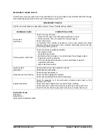
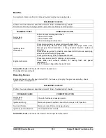
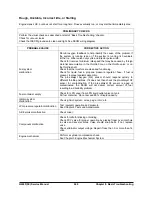
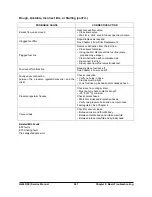
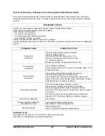
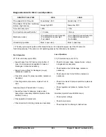
Cuts Out, Misses
Steady pulsation or jerking that follows engine speed, usually more pronounced as engine load increases,
sometimes above 1500 rpm. The exhaust has a steady spitting sound at idle or low speed.
PRELIMINARY CHECKS
Perform the visual checks as described at start of “ Basic Troubleshooting” chapter.
PROBABLE CAUSE
CORRECTIVE ACTION
Fuel system
malfunction
Check fuel system specifically for plugged fuel filter, low pressure.
Check for contaminated fuel.
Check injector drivers. Disconnect all injector harness connectors. Use
injector test light or equivalent 6-volt test light between the harness terminals
of each connector and observe if light blinks while cranking. If test light fails
to blink at any connector, it is a faulty injector drive circuit harness, connec-
tor, or terminal.
Check lock off intermittent connection.
Check dither valve operation.
Ignition system
malfunction
Check for spark on the suspected cylinder(s) using a shop oscilloscope or
spark tester or equivalent. If no spark, check for intermittent operation or
miss. If there is a spark, remove spark plug(s) in these cylinders and check
for cracks, wear, improper gap, burned electrodes, heavy deposits.
Check spark plug wires by connecting ohmmeter to ends of each wire in
question. If meter reads over 30,000 ohms, replace wire(s).
Visually inspect distributor cap, rotor, and wires for moisture, dust, cracks,
burns, etc. Spray cap and plug wires with fine water mist to check for shorts.
Check engine ground wire for looseness or corrosion.
Component malfunction
Check for electromagnetic interference (EMI). A missing condition can be
caused by EMI on the reference circuit. EMI can usually be detected by
monitoring engine rpm with Service Tool. A sudden increase in rpm with little
change in actual engine rpm indicates EMI is present. If problem exists,
check routing of secondary wires and check distributor ground circuit.
Check intake and exhaust manifolds for casting flash or gasket leaks.
Engine mechanical
Perform compression check on questionable cylinders. If compression is low,
repair as necessary.
Check base engine. Remove rocker covers and check for bent pushrods,
worn rocker arms, broken valve springs, worn camshaft lobes, and valve
timing. Repair as necessary.
Related MIL Faults:
EST faults
ETC Sticking fault
Summary of Contents for D20G
Page 2: ......
Page 5: ...Specifications TORQUE SPECIFICATIONS SB2004E00 D e c 1 9 9 8 ...
Page 14: ......
Page 16: ......
Page 138: ...Diesel Engine Engine System 124 NOTE The crankshaft must rotate freely by hand 02900058 ...
Page 254: ......
Page 256: ......
Page 260: ......
Page 341: ...4TNV98 4TNE98 Diesel Engine Section 3 Engine 87 4TNE98 Engine Figure 6 1 ...
Page 423: ...4TNV98 4TNE98 Diesel Engine Section 4 Fuel System 169 Fuel System Components Figure 7 1 ...
Page 477: ...4TNV98 4TNE98 Diesel Engine Section 7 Starter Motor 223 Starter Motor Troubleshooting ...
Page 494: ...4TNV98 4TNE98 Diesel Engine Section 8 Troubleshooting 240 Troubleshooting Charts ...
Page 495: ...4TNV98 4TNE98 Diesel Engine Section 8 Troubleshooting 241 ...
Page 496: ...4TNV98 4TNE98 Diesel Engine Section 8 Troubleshooting 242 ...
Page 498: ...4TNV98 4TNE98 Diesel Engine Section 8 Troubleshooting 244 4TNE98 Engine ...
Page 499: ...Service Manual G424FE LP Engine G424F LP Gasoline Engine G20G G25G G30G SB4320E00 Jan 2008 ...
Page 500: ......
Page 502: ......
Page 529: ...G424F FE Service Manual Chapter 2 Recommended Maintenance 29 ...
Page 534: ...G424F FE Service Manual Chapter 3 Engine Mechanical System 34 MAIN BEARINGS 0 50 UNDERSIZE ...
Page 584: ...G424F FE Service Manual Chapter 3 Engine Mechanical System 84 ...
Page 729: ...G424F FE Service Manual 229 Chapter 8 Basic Troubleshooting ...
Page 731: ...G424F FE Service Manual 231 Chapter 8 Basic Troubleshooting ...
Page 806: ......
Page 808: ......
Page 810: ......
Page 820: ...Power Train System Operation 14 Hydraulic System ...
Page 822: ...Power Train System Operation 16 Hydraulic System ...
Page 824: ...Power Train System Operation 18 Hydraulic System ...
Page 826: ...Power Train System Operation 20 Hydraulic System ...
Page 856: ......
Page 858: ......
Page 860: ......
Page 930: ......
Page 932: ......
Page 934: ......
Page 936: ......
Page 1018: ......
Page 1023: ...A374081 01 ELECTRIC SCHEMATIC MODEL D20 25 30G EM0K2 EM0K3 Cummins B3 3 ...
Page 1024: ...A654030 00 ELECTRIC SCHEMATIC MODEL D20 25 30G EM0QM EM0QN Yanmar 4TNE98 Tier 3 ...
Page 1025: ...A604500 00 ELECTRIC SCHEMATIC MODEL G20 25 30G EM0QF EM0QG GM G424F Non Certi LP ...
Page 1026: ...A604510 00 ELECTRIC SCHEMATIC MODEL G20 25 30G EM0QH EM0QJ GM G424F Non Certi GAS ...
Page 1027: ...A604516 00 ELECTRIC SCHEMATIC MODEL G20 25 30G EM0QY EM0QZ GM G424FE Tier 3 LP ...
Page 1028: ......
Page 1030: ......
Page 1059: ...Safety Section 29 Lean away from the direction of fall Lean forward ...
Page 1071: ...General Section 41 Typical Example Side Shifter Serial Number If Equipped ...


