G424F(FE) Service Manual
Chapter 9. Advanced Diagnostics
248
Chapter 9. ADVANCED DIAGNOSTICS
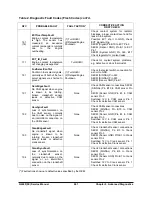
MI-07 systems are equipped with built-in fault
diagnostics. Detected system faults can be
displayed by the Malfunction Indicator Lamp (MIL)
as Diagnostic Fault Codes (DFC) or flash codes,
and viewed in detail with the use of the Service Tool
software. When the ignition key is turned on, the MIL
will illuminate and remain on until the engine is
started. Once the engine is started, the MIL lamp will
go out unless one or more fault conditions are
present. If a detected fault condition exists, the fault
or faults will be stored in the memory of the small
engine control module (SECM). Once an active fault
occurs the MIL will illuminate and remain ON. This
signals the operator that a fault has been detected
by the SECM.
Reading Diagnostic Fault Codes
All MI-07 fault codes are three-digit codes. When the
fault codes are retrieved (displayed) the MIL will
flash for each digit with a short pause (0.5 seconds)
between digits and a long pause (1.2 seconds)
between fault codes. A code 12 is displayed at the
end of the code list.
EXAMPLE :
A code 461 (ETCSticking) has been
detected and the engine has shut down and the MIL
has remained ON. When the codes are displayed
the MIL will flash four times (4), pause, then flash six
times (6), pause, then flash one time (1) This
identifies a four sixty one (461), which is the
ETCSticking fault. If any additional faults were
stored, the SECM would again have a long pause,
then display the next fault by flashing each digit.
Since no other faults were stored there will be a long
pause then one flash (1), pause, then two flashes
(2). This identifies a twelve, signifying the end of the
fault list. This list will then repeat.
Displaying Fault Codes (DFC)
from SECM Memory
To enter code display mode you must turn OFF the
ignition key. Now turn ON the key but do not start
the engine. As soon as you turn the key to the ON
position you must cycle the foot pedal by depressing
it to the floor and then fully releasing the pedal
(pedal maneuver). You must fully cycle the foot
pedal three (3) times within five (5) seconds to
enable the display codes feature of the SECM.
Simply turn the key OFF to exit display mode. The
code list will continue to repeat until the key is
turned OFF.
Clearing Fault (DFC) Codes
To clear the stored fault codes from SECM memory
you must complete the reset fault pedal maneuver.
CAUTION
Once the fault list is cleared it cannot be
restored.
First turn OFF the ignition key. Now turn ON the key
but do not start the engine. As soon as you turn the
key to the ON position you must cycle the foot pedal
by depressing it to the floor and then fully releasing
the pedal (pedal maneuver). You must fully cycle the
foot pedal ten (10) times within five (5) seconds to
clear the fault code list of the SECM. Simply turn the
key OFF to exit the reset mode. The code list is now
clear and the SECM will begin storing new fault
codes as they occur.
Summary of Contents for D20G
Page 2: ......
Page 5: ...Specifications TORQUE SPECIFICATIONS SB2004E00 D e c 1 9 9 8 ...
Page 14: ......
Page 16: ......
Page 138: ...Diesel Engine Engine System 124 NOTE The crankshaft must rotate freely by hand 02900058 ...
Page 254: ......
Page 256: ......
Page 260: ......
Page 341: ...4TNV98 4TNE98 Diesel Engine Section 3 Engine 87 4TNE98 Engine Figure 6 1 ...
Page 423: ...4TNV98 4TNE98 Diesel Engine Section 4 Fuel System 169 Fuel System Components Figure 7 1 ...
Page 477: ...4TNV98 4TNE98 Diesel Engine Section 7 Starter Motor 223 Starter Motor Troubleshooting ...
Page 494: ...4TNV98 4TNE98 Diesel Engine Section 8 Troubleshooting 240 Troubleshooting Charts ...
Page 495: ...4TNV98 4TNE98 Diesel Engine Section 8 Troubleshooting 241 ...
Page 496: ...4TNV98 4TNE98 Diesel Engine Section 8 Troubleshooting 242 ...
Page 498: ...4TNV98 4TNE98 Diesel Engine Section 8 Troubleshooting 244 4TNE98 Engine ...
Page 499: ...Service Manual G424FE LP Engine G424F LP Gasoline Engine G20G G25G G30G SB4320E00 Jan 2008 ...
Page 500: ......
Page 502: ......
Page 529: ...G424F FE Service Manual Chapter 2 Recommended Maintenance 29 ...
Page 534: ...G424F FE Service Manual Chapter 3 Engine Mechanical System 34 MAIN BEARINGS 0 50 UNDERSIZE ...
Page 584: ...G424F FE Service Manual Chapter 3 Engine Mechanical System 84 ...
Page 729: ...G424F FE Service Manual 229 Chapter 8 Basic Troubleshooting ...
Page 731: ...G424F FE Service Manual 231 Chapter 8 Basic Troubleshooting ...
Page 806: ......
Page 808: ......
Page 810: ......
Page 820: ...Power Train System Operation 14 Hydraulic System ...
Page 822: ...Power Train System Operation 16 Hydraulic System ...
Page 824: ...Power Train System Operation 18 Hydraulic System ...
Page 826: ...Power Train System Operation 20 Hydraulic System ...
Page 856: ......
Page 858: ......
Page 860: ......
Page 930: ......
Page 932: ......
Page 934: ......
Page 936: ......
Page 1018: ......
Page 1023: ...A374081 01 ELECTRIC SCHEMATIC MODEL D20 25 30G EM0K2 EM0K3 Cummins B3 3 ...
Page 1024: ...A654030 00 ELECTRIC SCHEMATIC MODEL D20 25 30G EM0QM EM0QN Yanmar 4TNE98 Tier 3 ...
Page 1025: ...A604500 00 ELECTRIC SCHEMATIC MODEL G20 25 30G EM0QF EM0QG GM G424F Non Certi LP ...
Page 1026: ...A604510 00 ELECTRIC SCHEMATIC MODEL G20 25 30G EM0QH EM0QJ GM G424F Non Certi GAS ...
Page 1027: ...A604516 00 ELECTRIC SCHEMATIC MODEL G20 25 30G EM0QY EM0QZ GM G424FE Tier 3 LP ...
Page 1028: ......
Page 1030: ......
Page 1059: ...Safety Section 29 Lean away from the direction of fall Lean forward ...
Page 1071: ...General Section 41 Typical Example Side Shifter Serial Number If Equipped ...


