background image


16 

DBC 130II   

DBC130II ISE41 

4. What's included


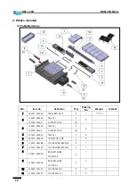
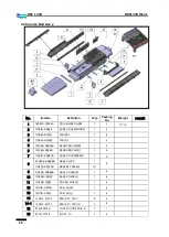
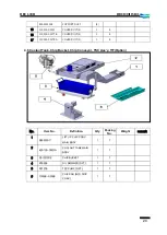
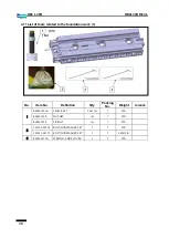
4.1 Table Bed Ass’y 


No. 

Item No. 

Definition


Q’ty 

Packing 

No. 

Weight 

remark 

160301-00136A 

TABLE BED ASSY 

1


17 Ton 


110961-00144D 

TRAY;(1) 

1


110958-01660   

SUPPORT,TRAY   

(1)


110961-00145D 

TRAY;(2) 

1


110958-01660   

SUPPORT,TRAY   

(2)


110961-00146C 

TRAY;(3) 

1


900115-00582A 

CONVEYOR,CHIP; 

1


110510-00428B 

COVER,SLIDE;(X4000)R 

1


110510-00427B 

COVER,SLIDE;(X4000)L 

1


110423-03265A 

BRACKET,SLIDE 

COVER;X-R 

2


110423-03266A 

BRACKET,SLIDE 

COVER;X-L 

2


10 

110508-10529C 

COVER;TRAY,(1) 

1


11 

110508-10530C


COVER;TRAY,(2)


1


Summary of Contents for DBC 130 II

Page 1: ...Installation Manual DBC 130Ⅱ Machine Tools ...

Page 2: ......

Page 3: ...Operator Part Option 25 4 9 Semi Splash Guard Magazine Part Option 27 4 10 Semi Splash Guard Table Part Option 28 4 11 List of tools related to the foundation work 1 30 4 12 List of tools related to the foundation work 2 31 4 13 BOLT KIT Shipping LIST 33 5 Installing the machine temporarily 36 5 1 Temporary installation of the column bed Z axis bed assembly 36 5 2 Temporary installation of the tab...

Page 4: ... Assembling and adjusting the Y axis 69 13 1 Installing the ball screw nut in the Y axis 69 13 2 Installing the Y axis taper gib and back plate gib 69 13 3 Installing the reference gib 70 13 4 Installing the ball screw nut 70 14 Machine Leveling 71 15 Precision Accuracy Correction 77 15 1 Straightness of Z axis 79 15 2 Straightness of X Axis 80 15 3 Straightness of Y Axis 81 15 4 Straightness of P...

Page 5: ...Carriage Magazine Side Home Position Setting 102 17 3 Setting the reference point for the tool magazine pot 106 17 4 Fine tuning the spindle side of the changer arm 110 17 5 Setting Parameter 7 Changer Movement 112 18 Installing the covers 113 18 1 Installing the table bed covers 113 18 2 Installing the column bed covers 114 18 3 Installing the column covers 115 18 4 Installing the semi splash gua...

Page 6: ... into consideration the dynamic relation between crane and foundation If a crane meeting the above specification is not available use alternatives such as a car crane large forklift etc for moving the machine 4 When determining the installation site refer to the machine layout diagram to secure room for installing the assemblies ATC electric cabinet hydraulic tank chip conveyor etc as well as enou...

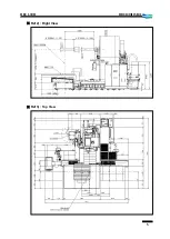
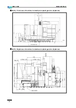
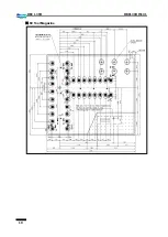
Page 7: ...5 DBC 130II DBC130II ISE41 Ref 2 Right View Ref 3 Top View ...

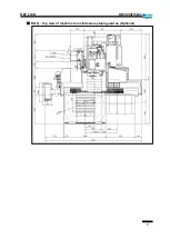
Page 8: ...6 DBC 130II DBC130II ISE41 Ref 4 Front view of machine to install semi splash guard on Optional Ref 5 Right view of machine to install semi splash guard on Optional ...

Page 9: ...7 DBC 130II DBC130II ISE41 Ref 6 Top view of machine to install semi splash guard on Optional ...

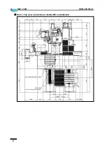
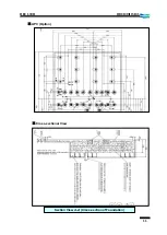
Page 10: ...8 DBC 130II DBC130II ISE41 Ref 7 Top view of machine to install APC on Optional ...

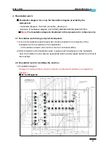
Page 11: ...oints 1 It is recommended to take at least a two month schedule from completion of the foundation work to completion of the installation It should take at least one month to cure the concreted surface 2 After completion of the foundation work measure each checkpoint on the foundation and if a problem is found take an appropriate action mostly repair before the arrival of the machine 2 2 Foundation...

Page 12: ...10 DBC 130II DBC130II ISE41 60 Tool Magazine ...

Page 13: ...11 DBC 130II DBC130II ISE41 APC Option Cross sectional View Section View A A Cross section of Foundation ...

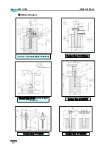
Page 14: ...2 DBC 130II DBC130II ISE41 Detailed Diagram Section View B B Main Unit Bed Section View C C Kicker Section View D D Center of Main Unit Bed Section View E E APC Section View G G APC Section View F F APC ...

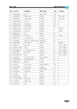
Page 15: ... Hex Socket Head BB 8 20 24 16 B26491363 Hex Bar 3 SM45C 1 MB46 18 S4001331 Hex Nut NA24 6 90 Tool Mag 19 250205 00953 Plate SS400 6 90 Tool Mag 20 B13593024A Foundation Collar SS400 6 90 Tool Mag 21 S3520376 Set Screw BQ 6 8 18 90 Tool Mag 22 B13593033B Bolt SM45C 6 90 Tool Mag 23 S0035252 Bolt Hex Head BA S24 130 6 24 B26491053A Adjusting Block SS400 6 25 B26491044 Bracket SS400 6 27 457845 Disk...

Page 16: ... Ø300mm to inject mortar into the second mortar surface in deeper than 400mm Important the tube must be removed after the first foundation work 6 The holes for the second mortar work should comply with the specifications in the detailed diagram above 7 When installing the machine temporarily use the adjusting bolt on the level block to make an approximate gap of 15mm ⓐ 8 The 6 level plate should b...

Page 17: ...Column Base 3 Column Body Ass y 6 000Kg Column Body 4 Spindle Head Ass y 2 500Kg Spindle Head 5 ATC Ass y 3 000Kg ATC Tool Magazine Tool Magazine Base 6 Others 3 500Kg Electric Cabinet Hydraulic Unit Oil Cooler Duct Covers Chip Conveyor and Accessories Total weight of machine 43 000Kg The above list is for the standard equipment and is subject to change without notice for reasons of customer speci...

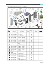
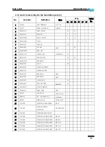
Page 18: ... 1 8 110958 01660 SUPPORT TRAY 1 3 110961 00145D TRAY 2 1 8 110958 01660 SUPPORT TRAY 2 4 110961 00146C TRAY 3 1 8 5 900115 00582A CONVEYOR CHIP 1 8 6 110510 00428B COVER SLIDE X4000 R 1 1 7 110510 00427B COVER SLIDE X4000 L 1 1 8 110423 03265A BRACKET SLIDE COVER X R 2 7 9 110423 03266A BRACKET SLIDE COVER X L 2 7 10 110508 10529C COVER TRAY 1 1 8 11 110508 10530C COVER TRAY 2 1 8 ...

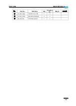
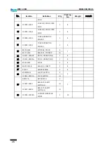
Page 19: ... Weight remark 12 110961 00183 COVER CENTER 1 8 13 110508 11089C COVER REAR 1 8 14 110423 03095A BRACKET TRAY 2 8 110958 01647A SUPPORT TRAY 2 14 1 110423 03095A BRACKET TRAY 1 8 15 230104 01477 BUCKET OIL 1 8 16 L56301092B STAND FLOOR 3 8 17 150119 00381 PAN OIL 1 8 ...

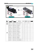
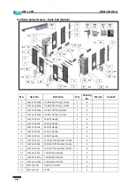
Page 20: ...02B REMOVER CHIP R 1 8 6 101556 00348 REMOVER CHIP L 1 8 7 110510 00020A SLIDE COVER REAR 1 2 8 250205 00868A BASE PLATE 1 8 110423 03229A BRACKET FRAME 1 9 110508 00986B BASE COVER R 1 8 10 110508 10915C BASE COVER L 1 8 11 110508 12561 COVER CHIP 2 1 8 12 150119 00100 PAN OIL R 1 8 13 150119 00101 PAN OIL L 1 8 14 110423 03780 BRACKET TRAY 8 8 14 1 110423 03799 BRACKET TRAY 2 1 8 15 B26280544B C...

Page 21: ...19 DBC 130II DBC130II ISE41 No Item No Definition Q ty Packing No Weight remark 17 111001 00063 PROTECTOR CHIP 1 8 18 110423 03590 BRACKE PLATE BASE 4 8 19 B13210193A POSITION_BLOCK 1 7 ...

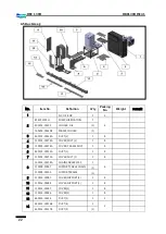
Page 22: ... UPPER COVER 1 8 6 160609 02657 FRAME SIDE COVER 1 8 110517 00573B COVER SIDE R U 1 110517 00574B COVER SIDE R B 1 7 110508 10978A COVER FRONT MIDDLE 1 8 8 110508 10625B COVER FRONT R U 1 8 9 110508 10626C COVER FRONT R B 1 8 10 110508 10622 COVER FRONT U 1 8 11 110508 10624B COVER FRONT B 1 8 12 110517 00571B COVER SIDE L U 1 8 13 110517 00572B COVER SIDE L B 1 8 14 110508 12560 COVER CHIP 1 1 8 ...

Page 23: ...LOWER 1 7 B14115063A B25116063B GIB LOWER 1 7 250205 01098 B25116013A PLATE BACK 1 1 7 B14115083A B25116083B GIB UPPER 1 7 B14115053A B25116053B GIB UPPER 1 7 250205 01099 B25116023A PLATE BACK 2 1 7 B14115083A B25116083B GIB UPPER 1 7 B14115053A B25116053B GIB UPPER 1 7 250205 01098 B25116013A PLATE BACK 1 1 7 B14115073A B25116073B GIB LOWER 1 7 B14115063A B25116063B GIB LOWER 1 7 B25116033B B251...

Page 24: ...0505 00276A COVER DUCT 2 1 8 5 110505 00274A COVER FRAME DUCT 1 8 6 460103 00533A DUCT 1 1 8 7 110505 00275A COVER DUCT 1 1 8 8 130301 00254A CHAIN CABLE Z2000 1 6 110958 01897 SUPPORT CABLE CHAIN 1 110958 01903 SUPPORT FRAME 1 9 110516 00089 COVER SUPPORT 4 1 8 10 110516 00088 COVER SUPPORT 3 1 8 11 110516 00087 COVER 1 1 8 12 110516 00086 COVER 2 1 8 13 460103 00656 DUCT 3 1 2 14 460103 00536B D...

Page 25: ...ER DUCT 5 1 8 4 6 Coolant Tank Chip Bucket Chip Conveyor TSC Ass y T F Option No Item No Definition Q ty Packing No Weight remark 1 B26575011 LIFT UP CHIP CONV MAIN BODY 1 7 2 450102 00131A COOLANT TANK MAIN BODY 1 7 3 C51221011E CHIP BUCKET 1 7 4 R76595 OIL SKIMMER OPT 1 7 5 R37278 TSC PUMP OPT 1 7 6 101558 00168 CHIP PAN W O CHIP CONV 1 7 ...

Page 26: ...ption No Item No Definition Q ty Packing No Weight remark 1 100702 00154 40TOOLS MAGAZINE 1 5 2 4Ton 100702 00172 60 90 TOOLS MAGAZINE 1 5 4 5Ton 2 860103 00533A FIXTURE MAGAZINE 1 2 860103 00637 FIXTURE MAGAZINE 1 2 3 160101 00277C TOOL MAGAZINE BASE 1 5 ...

Page 27: ... 4 1 8 5 102302 00149B FENCE OPERATOR 5 1 8 6 102302 00145B FENCE OPERATOR 1 1 8 7 102302 00171A FENCE OPERATOR 2 1 8 8 102302 00144A FENCE ROTATING OPERATOR 1 8 9 910801 00029A ROOF OP DOOR 2 1 8 10 910801 00030A ROOF OP DOOR 3 1 8 11 910801 00034 ROOF OP DOOR 1 1 8 12 R70180 HANDLE 2 7 13 LAMP 1 6 14 110922 00564 GUIDE DOOR 2 1 8 15 110922 00563 GUIDE DOOR 1 1 8 16 110508 11065 COVER 4 FENCE OPE...

Page 28: ...ERATOR FENCE 1 1 8 22 B31722324 STOPPER DOOR 4 7 B31722314 BRACKET STOPPER 4 23 102301 00099B DOOR OPERATOR 2 1 8 24 102301 00098A DOOR OPERATOR 1 1 8 25 B13722023 PLATE 2 8 26 B13721313B GLASS 1 SAFETY 2 8 27 R70177 HINGE SPRING 4 8 28 ESWSF0013 SAFETY SWITCH 2 6 110423 02251A PLATE SWITCH 2 29 R87057A KEY SWITCH 2 7 110423 03897 BRACKET SAFETY SWITCH 3 2 110423 03896 BRACKET SAFETY SWITCH 2 2 30...

Page 29: ... COVER TOP 1 8 4 110958 02118 SUPPORT 1 8 5 102302 00154A FENCE ATC 3 1 8 6 110508 10979A COVER ATC FENCE 1 8 7 160629 00005 FOOT LEVELING 1 SET 8 8 102302 00172 FENCE ATC 1 1 8 9 102302 00151A FENCE ROTATING 1 8 10 102302 00169 FENCE ROTATING 1 8 11 500119 00154 GLASS SAFETY 1 8 12 250205 00096 PLATE GLASS 1 8 13 110423 03695 BRACKET 1 8 14 R70177 HINGE SPRING 7 8 15 110958 01929A SUPPORT ATC FEN...

Page 30: ...LE 1 8 5 102302 00207 FENCE TABLE 2 1 8 6 102302 00206 FENCE TABLE 1 1 8 7 102302 00208 FENCE TABLE 3 2 8 8 102302 00209 FENCE TABLE 4 1 8 9 102302 00210 FENCE TABLE 5 1 8 10 102302 00167 FENCE ROTATING SEMI TABLE 1 8 11 102302 00168 FENCE ROTATING SEMI TABLE 1 8 12 102302 00166 FENCE ROTATING SEMI TABLE 1 8 13 110508 12426 COVER FENCE TABLE 2 8 14 110508 12427A COVER FENCE TABLE 2 8 15 110508 124...

Page 31: ...OPPER 4 110956 00318 STOPPER DOOR TABLE 4 110508 14722 COVER LM 2 20 250205 01144 PLATE PACKING 2 2 8 21 250205 00984A PLATE PACKING 2 8 22 400606 00675 PACKING 2 7 23 120203 00418 CLAMP 2 8 24 110933 00036 LATCH 2 8 25 R70165 HANDLE 2 7 26 110927 00258 HINGE 7 8 27 110927 00259 ROTATING HINGE 6 8 28 110508 12429 COVER DOOR 2 8 29 110508 14154 COVER DOOR ROTATING 1 1 8 30 110508 12439B COVER DOOR ...

Page 32: ...rk 1 No Item No Definition Q ty Packing No Weight remark 1 B26491313A LEVEL BOLT 1 Set 6 7 STD B26491334 NUT HEX 6 7 STD B26491514 FIX BOLT 6 7 STD 2 120112 01326 BOLT NUT WASHER SET 1 7 STD 120112 01327 BOLT NUT WASHER SET 1 7 SEMI S G 3 B26491373A WRENCH SLIDE COVER 1 7 STD ...

Page 33: ...CK 20 7 14 B26491293 FUNNEL CONCRETE 1 7 15 B26491353 CENTER ANCHOR 7 7 16 B26491363 BAR HEX 3 NA46 1 7 17 B26491393 BAR HEX 4 NA24 1 7 18 B26491423 LEVEL PLATE 42 7 19 B26491444 BOLT HEX HEAD BA24X260 42 7 20 C60148071C STAND WORKING 1 1 7 21 P70600075 BAND HOSE HB75 1 7 22 R27227 HOSE DUCT VFM 70 64 1 7 23 R80013C KIT TOOL BOX 공구통 L31900021 1 7 24 R80037 GREASE GUN MODEL 12228 1 7 25 T6510022 SP...

Page 34: ...R DOUBLE ENDED MB22X24 1 7 37 T6510081 SPANNER DOUBLE ENDED MB24X27 1 7 38 T6530028 COMBINATION WRENCHES MS36 1 7 39 T6550015 L WRENCH MP14 SCM3 1 7 40 T6550018 WRENCH KEY HEX ONG MP17 SCM3 1 7 41 T6550020 L WRENCH ONG MP19 SCM3 1 7 42 T6550022 L WRENCH ONG MP22 SCM3 1 7 43 T6600388 SOCKET 3 4X30 1 7 44 T6600400 SOCKET 3 4X36 1 7 45 T6750004 HANDLE RATCHET DES T0675 1 7 46 T7050011 DRIVER SCREW 6x...

Page 35: ... 11 S2204862 BB6X20 40 STD GEAR BOX COVER결합용 COLUMN COVER 12 S2205062 BB6X25 10 STD COLUMN BASE상면의 PLATE 고정용 13 S2205462 BB6X40 40 STD COLUMN COVER 14 S2208862 BB8X20 30 STD PIPE SUPPORT BRACKET 고정용 SEMI 15 S2209062 BB8X25 20 STD DUCT BRACKET Z축 SLIDING COVER 16 S2212262 BB10X30 45 STD SLIDING COVER BRACKET 17 S0005052 BAS6X25 10 STD 18 S0005352 BAS6X35 10 STD 19 S0009052 BAS8X25 10 STD SPINDLE HE...

Page 36: ...AR BOX COVER결합용 COLUMN COVER 13 S2205062 BB6X25 10 STD COLUMN BASE상면의 PLATE 고정용 14 S2205462 BB6X40 40 STD COLUMN COVER 15 S2208862 BB8X20 80 SEMI PIPE SUPPORT BRACKET 고정용 SEMI 16 S2209062 BB8X25 60 SEMI DUCT BRACKET Z축 SLIDING COVER 17 S2209262 BB8X30 10 SEMI SEMI S G 18 S2212262 BB10X30 45 STD SLIDING COVER BRACKET 19 S0005052 BAS6X25 10 STD 20 S0005352 BAS6X35 10 STD 21 S0009052 BAS8X25 10 STD S...

Page 37: ...35 DBC 130II DBC130II ISE41 No Item No Spec Q ty Option Location 36 S5100301 ZS6 150 SEMI 37 S5100501 ZS8 250 SEMI 38 S5100601 ZS10 60 STD ...

Page 38: ...grout and drain the water right before the injection If 30 days or more have passed since constructing the foundation concrete soak it in water for over 24 hours This is to enhance the adhesiveness of the injected grout and to prevent the grout from drying too quickly as well as to improve the fluidity of the grout 22 Locate the foundation component box from the shipping package and prepare for in...

Page 39: ... area Stop lifting the Z axis bed column bed assembly at an appropriate height for the following work For your safety it is recommended to prop up the bed with a strong support Remove rust impurities cuts or paint spots that may remain in the level block installation site using the whetstone sandpaper or file 6 Insert B26491014 adjusting bush and B26491204 washer into every anchor hole in the bed ...

Page 40: ...cilitate the work install the level plate first and insert the level block between bed and level plate Ensure that the level block should keep in parallel with the bed to the end Then tight up the bolt 8 Place B26491223 block under the temporary bolt site of the bed and put down the column bed slowly Level Block Level Plate Anchor Block Temporary Bolt Check the gap ...

Page 41: ... X axis bed assembly 1 Make preparations for temporary installation by referring to the Temporary installation of the column bed Z axis bed assembly section above Lift up the table bed assembly with the crane or forklift and move it to the temporary installation site Weight Approx 17 tons Rope hooking Position 4 places in both sides of the bed 2 Smooth the surface of the level block installation a...

Page 42: ...the bed to the end Then tight up the bolt 4 The three level blocks that are attached to the Z axis bed see the picture below should be tilted to avoid an interference with each other Place B26491223 block under the temporary bolt site on the bed and put down the table bed slowly 5 Smooth the installation surface of X axis bed and Z axis bed using the whetstone and insert the fixing bolt into the Z...

Page 43: ...he foundation hole Note that you should apply even force to every temporary bolt and perform the leveling alternately on both ends of the bed 8 When the temporary leveling work on the table bed X axis bed comes close to the end try shaking 2 liners in the concatenating sites between X axis and Z axis beds to check if the gaps match If no problem is encountered tighten up the fixing bolts and check...

Page 44: ...n move the tool magazine alone aside for later work Remove the eyebolts after installing the magazine Weight approx 2 4 tons 2 Installing the tool magazine bracket Install the magazine bracket in the intended side of the column bed 3 Installing the tool magazine anchor Use the crane to lift up the tool magazine base as appropriate and fit the bolts into the level plate see the Foundation Detailed ...

Page 45: ...magazine bracket place the tool magazine base on the block under the temporary bolt site Place the level on the tool magazine base in the X and Z directions Set an approximate level of the tool magazine base and fit the bolt holes between tool magazine bracket and installation sites Then tighten the fixing bolts ...

Page 46: ...rder to reinforce the adhesiveness between concrete wall that was constructed in the primary foundation work and secondary grout 2 Has foreign matter inside of each foundation hole been completely removed Rid the hole of any concrete debris or bits of flexible tubes used in making the foundation hole 3 Has each foundation hole been soaked in water This is very important because it is to improve th...

Page 47: ... bubbles in the bottom of the level plate while drying It is recommended to use a beaker to measure the amount of water Water amount 3 75 4 0 L per a 25 kg sack water ratio 15 16 3 A mixture of water and grout must be injected completely within 30 minutes after the mixing Otherwise the mixture may cause a chemical reaction 4 When grouting the desirable temperature of the mixture is between 10 and ...

Page 48: ...the grout mixture so that the mixture fills up the whole hole evenly without the buildup of air bubbles 3 Clean up the floor when the foundation holes are filled up with grout Pour the grout mixture at an average of 40 mm above the level plate Make sure there is no gap between foundation surface and level plate keep an eye on the rear plate which is barely noticeable Inject grout after completing ...

Page 49: ... a generous schedule for curing The longer the curing period is the greater the strength Assign at least 5 days for grout curing 7 days is recommended Allow additional 2 or 3 days for curing in the winter 3 Keep vibrations shocks and loads to a minimum level and maintain the ambient temperature above 10 C for the curing period When it is too low in temperature in the winter season use a heater or ...

Page 50: ...olts on the top of the column and crane and slowly erect the column Considering the weight of the column 6 tons use strong ropes to withstand the weight When the column is erected adjust the length of the rope so that it does not interfere in the servo motor The column may be very unstable when it is just about to stand up mostly due to the inertial force To prevent this prepare an additional wood...

Page 51: ... the column when it nearly contacts on the base and tighten the reamer bolts first and go on with the other bolts Then resume lowering the column onto the bed Insert the column adjusting block and use the adjusting bolt to set the approximate position of the column Then tighten the fixing bolt Reamer Bolt ...

Page 52: ... the spindle head in a wider area 2 Wipe up the turcite and gib installation site of the spindle head before applying grease Don t forget to clean up the grinding side of the column and apply grease too 3 Lift up the spindle head and put it down in contact on the column 4 Install 4 back plates so that the number marked on each gib already assembled into the back plate matches with the number marke...

Page 53: ... already arranged on the top and bottom of the spindle head to the sleeve of each applicable gib 8 When you have installed the back plate gibs lubricant pipes and Y axis clamp assembly turn the ball screw nut manually to lower it at an appropriate position Then tighten the fixing bolt Remove the eyebolt to disconnect the crane Back Plate Gib Taper Gib Back Plate Gib Reference Gib Distributor ...

Page 54: ...is process does not proceed as intended insert a strong support between spindle head and column base and remove the eyebolt Then turn on the machine and lower the ball screw nut in Handle mode to mount it onto the spindle head Support ...

Page 55: ...g the hydraulic power unit electric cabinet OP box and ducts 5 Duct 7 Piping Frame 2 Duct 4 Duct 1 Electric Cabinet 1 Electric Cabinet 7 Piping Frame 2 Duct 4 Duct 5 Duct 3 Duct 3 Duct 6 Duct 8 Cable Chain Support 6 Duct 8 Cable Chain Support ...

Page 56: ... unit and lubricant unit are already installed Install the height bolt and adjust the height from the duct using the bolt 4 Lift up electric cabinet 1 and OP box with care of the balance and install the height bolt on the bottom Adjust the height and horizontal vertical positions based on duct 2 and bed 5 Adjust the position and height of ducts 4 5 and 6 so that they align with the cable chain sup...

Page 57: ...that you can connect them in their respective position correctly 1 Arranging wires from the table bed 2 Arranging wires around the column 3 Connecting wires to the spindle head Stretched out wires Wiring in the terminal box Stretched out wires Connectors in the terminal box Connecting the W axis servo motor connector ...

Page 58: ...ion 5 Connecting the wires inside the electric cabinet 1 Apply power in the duct s direction 2 Apply power in the upper direction 3 Apply power in the lower direction Connecting the scale cable connectors Completed Connecting the power cable and connectors Connecting the wires inside the electric cabinet ...

Page 59: ...wires to each applicable servo motor 7 Arranging wires for the column bracket 8 Connecting the scale feedback cables to each axis Servo Motor in the X axis Servo Motor in the Z axis Servo Motor in the Y axis Servo Motor in the W axis Y axis X axis ...

Page 60: ...58 DBC 130II DBC130II ISE41 Z axis ...

Page 61: ...es When connecting the hoses ensure that the number marked on the manifold matches with the number tag attached to the hose Make connection one by one in an orderly manner and take caution not to leak the oil pressure 1 Spindle Head Tail Bracket 2 Column Manifold 3 Duct ...

Page 62: ...azine wires and hydraulic hoses Put the tool magazine on the top of ATC base or move the wires and hoses close to the base and plug in the connectors and connect the hoses hydraulic lubricant and air Scale Air Hyd Line P Hyd Line T Air Line Lub Line TMG 용 전선 Connector ...

Page 63: ...t clamps Remove the transit clamps that are designed to prevent the slippery table or column base by factory default X axis front fixture X axis rear fixture Z axis fixture Front fixture in X axis X axis rear fixture X axis rear fixture Z axis fixture ...

Page 64: ...2 Type of Oil HM32 Oil 3 Fueling Capacity 37 5L 9 2 Oil Cooler Tank 1 Position Piping Frame 2 Type of Oil FC10 Oil 3 Fueling Capacity 45L 9 3 Table 1 Position Rear of the table base 2 Type of Oil GH68 Oil 3 Fueling Capacity 40L 9 4 Lub Tank 1 Position Piping Frame 2 Type of Oil G220 Oil 3 Fueling Capacity 25L ...

Page 65: ...st run on the spindle at 30 to 50 of the max speed 9 6 Air Service Unit Oiler Tank 1 Position Air service unit in the side of piping frame 2 Type of Oil HM32 Oil 3 Fueling Capacity 50cc Since the oiler is not equipped with an oil gauge check and refill the tank on a regular basis if necessary If operated without oil for an extended period of time all air lines and air driven components air solenoi...

Page 66: ...ce unit in the piping frame in the rear of the machine 1 Use an air hose or a tube with its inner diameter of at least 9mm 2 The pressure of air source should be at least 0 55Mpa 0 76Mpa 3 Use only dehydrated clean air and if the air contains moisture make sure to install an air dryer Air Consumption Standard Optional Air blow ATC Option Scale ATC Option blow scale ATC DBC 110S 520 820 740 1020 DB...

Page 67: ...will contain water inside affecting the performance of the machine However if this happens ask the installer to install the pipeline again as instructed above 2 The pipeline from the site ceiling is then connected to the machine through a distribution tank that filters the water generated from compressed air It is advisable to use an air dryer such as the distribution tank 3 Use an air hose or tub...

Page 68: ...e switch connecting from the electric cabinet to the machine to turn off the power and then switch the U and W wires of the main power supply wires with each other 3 Once the rotating direction of the motor is determined press NC Power On and Machine Ready in sequence When the hydraulic motor starts running check if there is a problem in the overall operation specifically in the hydraulic hoses or...

Page 69: ...ydraulic pump 2 Main Air 0 5 0 6MPa 5 6bar 3 Oil Cooler 0 7MPa 7bar 4 Pressure of the lubrication pump 15Kg cm 15bar Check when the pump is operating If the pressure is below the specified level it indicates that there is an oil leak in the lubrication line Check the line and take an appropriate action if necessary ...

Page 70: ...ump 1 0Kg 1bar 6 Oil pressure on the table gear box 10Kg cm 10bar 7 Spindle Air Oil Operation Pressure 16bar 8 Scale Air Operation Pressure 1 bar Adjust the pressure using the wheel as shown Table Lub Pump Gear Box 유압 Pressure Gage Lub Pressure valve ...

Page 71: ...Slowly tighten the BB bolt one of the gib adjusting bolts at first Then tighten it up when you feel that the gib gets tightened this is where the gap between gib and column sliding side becomes 0 4 Then loosen the bolt BB bolt by a half turn 180 5 Tighten back the set screw BQ bolt and pull out the gib as much as you have loosened the BB bolt 180 6 Adjust the upper and lower gibs as well as the ot...

Page 72: ...bs 13 4 Installing the ball screw nut 1 Move the Y axis to Y0 2 Slightly loosen the ball screw nut fixing bolts on the Y axis 3 Apply force as even as possible to each bolt until you tighten them up finally Alternatively you can tighten up two diagonal bolts first and loosen them slightly Then tighten them up finally Reference gib Fixing Bolts x2 ...

Page 73: ...ial care must be taken Preparation Spindle Test Bar Square 500 500 Magnetic Square Level 150 150 Test Indicator 0 02mm 1m Magnetic Stand Other Leveling Tools Spanner 24mm 36mm Pipe 1 1 5m No Description Picture Specification 1 Spindle Test bar BT50 YM10609011 2 Granite Master Angle Square 500 X 500 X 60 3 Magnetic Type Precision Square Level 1div 0 02mm 1m 4 Test Indicator 1div 0 02mm 1m 5 Magneti...

Page 74: ...level Turn the level by 180 degrees and read the gradation in the same direction With a plain screwdriver adjust the reference point screw to set the level to an intermediate gradation between initial gradation before rotation and gradation after 180 degrees of rotation Repeat steps through above until rotation in either direction comes up with the same result How to read the gradation Right end o...

Page 75: ...01 M01 M01 X750 X3000 X750 M01 M01 M01 X1500 X2250 M99 M01 M01 Precautions for the leveling work Apply force as evenly as possible to each level block adjusting bolt so that the level blocks contact on the bed evenly If any one of the level blocks contacts on the bed unevenly it may cause an incorrect leveling in the end The last step of the leveling should be ended in the direction that the level...

Page 76: ...he set level Then tighten the nut Setting the reference point for the Z axis level Place the level in either side of the column and read one end gradation of the water bubble of the level Turn the level by 180 degrees before moving to the opposite side of the column Then read the gradation in the same direction With a plain screwdriver adjust the reference point screw to set the level to an interm...

Page 77: ...mended to place another level on the table for your reference It is recommended to make coordinate settings for the leveling in advance Setting example O 002 G90 G00 G54 Z0 Z1200 Z800 M01 M01 M01 Z400 Z1600 Z400 M01 M01 M01 Z800 Z1200 M99 M01 M01 7 Take a note of the leveling values while repeating the leveling on both X and Z axes until the overall difference of the leveling falls below 0 02 m To...

Page 78: ...target perform the static accuracy inspection of the machine before locking the anchor nut If you find an error use the level to correct it refer to static accuracy inspection and correction below 9 When the static accuracy of the machine falls below the specified tolerance tighten the anchor nuts starting from the X axis The leveling target above is the measurement after the machine static accura...

Page 79: ...01 PALLET 2 0 001 5 Squareness between coordinate axis 0 001 0 001 0 001 X Y M DMF Q7200 5 1992 2 10 A4 210 297mm Doosan Infracore Co Ltd 0 030 m 0 030 m NO Items Tolerance 0 010 500 X Y DB130C CM CX DB250C CM 0 030 full stroke X Z Data Sheet 0 010 500 0 010 500 0 010 500 0 030 full stroke 0 030 full stroke 0 030 full stroke 0 001 0 001 X Y 0 020 500 0 020 500 Y Z X Z X Y Y Z X Z Y Z 0 020 500 Y Z...

Page 80: ...1 PALLET 2 0 001 10 Difference in height of Y axis when changing the pallet 0 001 11 Parallelism between Z axis movement center line of main spindle 0 001 0 001 12 Shaking inside the main spindle hole Front end of the 0 001 spindle At 300 mm 0 001 13 Displacement of main spindle movement to Z axis M DMF Q7200 5 1992 2 10 A4 210 297mm Doosan Infracore Co Ltd 0 001 0 001 0 020 500 0 040 full stroke ...

Page 81: ... Z ⓐ Measure Install the straight edge horizontally on the pallet in the Z axis direction and install the indicator on the spindle head Set either end of the straight edge to 0 and move the Z axis to check the greatest difference measurement in the middle of the movement If the straight edge is not available use the sides of the square that is required for measuring the squareness between X and Y ...

Page 82: ... and perform the leveling again 3 X Z ⓐ Measure Install the straight edge horizontally on the pallet in the X axis direction and install the indicator on the spindle head Set either end of the straight edge to 0 and move the X axis to check the greatest difference measurement in the middle of the movement If the straight edge is not available use the sides of the square that is required for measur...

Page 83: ...ce gib in the front and lower of the spindle head 2 Loosen the set screw BQ bolt of the gib adjusting bolts completely 3 Slowly tighten the BB bolt one of the gib adjusting bolts at first Then tighten it up when you feel that the gib gets tightened this is where the gap between gib and column sliding side becomes 0 4 Then loosen the bolt BB bolt by a half turn 180 5 Tighten back the set screw BQ b...

Page 84: ...ightness of Pallet Deck 1 X Y direction 2 X Z direction ⓐ Measure Install the straight edge on the table deck in the X axis direction X Y or in the Z axis direction Y Z and install the indicator on the block Measure the greatest difference in straightness of the top side of the straight edge If the straight edge is not available you can install the indicator on the spindle head and manually move t...

Page 85: ...sure the parallelism between square graplate and X axis Take a note of the difference and direction 2 Then present the indicator to the square graplate in the Y axis direction and measure the overall squareness Take a note of the difference and direction 3 Set the bottom of the square graplate to 0 and move up and stop the Y axis at the top of the square graplate Tighten the level block evenly on ...

Page 86: ...erform the scraping of the column base sliding plate Preparations Scraper whetstone minium screw jacks x2 cloth other repair tools 1 Unplug the cable that supplies power to the lubricant motor from the electric cabinet to block lubricant inflow Turn off the power and unplug the secondary U51 and V51 wires from the terminal block 2 Remove the front sliding cover and rear cover from the Z axis 3 Loo...

Page 87: ...en completed clean up the area of your work and apply grease before putting all removed parts back together 14 Move the Z axis to 0 Apply force as evenly as possible to each of the ball screw nut fixing bolts until you tighten them up finally 15 Put all removed parts and covers for the precision work back together 3 X Z squareness ⓐ Measure Place the square on the table deck in the X axis directio...

Page 88: ...gain 6 If no error is found measure the X and Z axis levels as well as the squareness of each axis again 15 6 Parallelism of movement to X Z axis parallelism of pallet deck and shaking of index table 1 X axis direction Measure Install the indicator at the end of the spindle and place the height measuring block 500mm away from the table center in the X and Z directions before setting the reference ...

Page 89: ...scratches 7 Insert the bolt BB 12 100 in the middle of the sliding plate and use the bolt as a handle to remove the sliding plate from under the table base 8 Clean up the sliding plate and apply minium 9 Wrap a thin tool ex scraper with a clean cloth to wipe up the bottom and the grinding side of the table base Clean it up Even a slightest lubricant is not allowed to remain 10 Insert the sliding p...

Page 90: ...xis to 0 Install the indicator at the end of the spindle and move the Z axis to Z0 Check the distance between indicator and table center and move the Z axis back as much as that distance Place the measuring block on it and set the reference point 2 Then move the Z axis back to Z0 and use the block to measure the height 3 Adjust the level block in the front position of the table bed evenly to fit t...

Page 91: ... deck So if you want to correct the shaking you should scrape the bottom or grind the deck as appropriate 15 7 Squareness in division of index table 1 How to measure 1 Place the square horizontally on the table deck While moving the X axis correct the parallelism between square and X axis To correct the parallelism use the handle of a screwdriver to impact on certain points of the square 2 While i...

Page 92: ... for the B axis The overall gear ratio of the B axis is 1440 1 That means that the B axis rotates once when the servo motor revolves 1440 times so the maximum degree of the B axis per one revolution of the servo motor is 0 25 Thus the grid shaft should be adjusted within 125 1 Set the reference point for the B axis 2 Install the indicator on the spindle present the gauge to the table T hole or the...

Page 93: ...ten up the locating bush fixing bolts applicable bolts only 5 Perform the table unlocating and turn the table to tighten up the bush bolts Then reset the B axis reference point before performing the table locating to check if there still occurs an interruption 6 While indexing the B axis by each 90 correct the positions of the other three locating bushes respectively 7 When done place the square h...

Page 94: ...0mm away 2 Loosen the bolts 10 BA24 100 except for the reamer bolts in the front right side of the column 3 Use the adjusting bolt on the position block under the column to move the column in the opposite to the indicator direction about 5 times as much as the error 4 Repeat these instructions above until you get a satisfactory result 5 When completed tighten the adjusting bolts x2 evenly and tigh...

Page 95: ...ded to the parallelism error Install the indicator and use the block gauge to set the thickness of the parallel gib Then scrape the gib according to the calculation approximately 2 5 times as much as the value measured by the test bar 2 Adjusting the gap for the taper gib Loosen the bolts on the reference gib in the front and lower of the spindle head Loosen the set screw BQ bolt of the gib adjust...

Page 96: ...the sandpaper to grind the contact area of the taper Using the grinder is strictly prohibited If the taper side is badly damaged re grind the spindle itself 15 11 Movement of spindle in the Z axis direction 1 How to measure Insert the test bar into the spindle insert the steel ball into the end center of the test bar and present the indicator to each of X and Y highest points While rotating the sp...

Page 97: ...ifference between current position and W700 in the parameter 1850 Z field To change the W axis grid shift parameter Read the measuring value of the machine position coordinates displayed on the CRT monitor and enter the positive parameter in micron μ if it s greater than 700 or the negative parameter if less than 700 Add or deduct the above measurement to and from the existing parameter and enter ...

Page 98: ...bar 6 Move the Y axis and stop moving it when the needle is positioned at the highest point of the test bar Do NEVER move the X axis 7 Rotate the spindle and stop rotating it at the intermediate point of the test bar runout Then set the gauge to 0 8 Move the Z axis in direction by 400mm and rotate the B axis by 180 degrees 9 Move the Z axis back in direction and stop right before the test bar cont...

Page 99: ...machine position coordinates displayed on the OP screen Enter the positive parameter if the result of deducting half of the X stroke 1500 from the machine position is a positive value enter the negative parameter in micron μ if the result is a negative value Add or deduct the above measurement to and from the existing parameter and enter INPUT or enter the result plus the symbol and press INPUT Pa...

Page 100: ... above measurement to and from the existing parameter and enter INPUT or enter the result plus the symbol and press INPUT Add or deduct the above measurement to and from the existing parameter and enter INPUT or enter the result plus the symbol and press INPUT Parameter for the Z axis reference point NO 1850 Z Z290 Is the result where the test bar is 310mm long L and 60mm wide D i e Z L H W D 2 Z ...

Page 101: ...ween table deck and center of the spindle is 250mm Formula Y L D 2 250 4 Install the indicator on the top of the test bar and rotate the spindle while reading the runout on the test bar Stop rotating the spindle at an intermediate value of the runout 5 Move the Y axis to set the indicator needle to 0 6 Check the measuring value of the machine position coordinates displayed on the main OP screen an...

Page 102: ...s Remove all the temporary blocks that you placed in advance for the temporary installation 3 Use ATC adjusting bolts to adjust the vertical horizontal and front rear positions of ATC based on ATC rail Adjusting the ATC height Use the height bolt to adjust the height and straightness based on the rail section spreading between ATC rail and column Use the iron rule or special metal bar to measure t...

Page 103: ...ificantly from the height difference use the height bolt to adjust the height between two rails first When you are sure about the height front rear position left right position and straightness between two rails tighten all the height bolts evenly by a half turn and tighten all the fixing bolts Check the height front rear position left right position and straightness between two rails again and fi...

Page 104: ...ove the changer to the magazine pot manually jog mode 3 Open the door of the electric cabinet and find the carriage AMP that is located in the inner front side 4 1 Check the center position using the centering fixture above and if it fits correctly Press the MODE key on the start screen r0000 of the servo drive to switch to the diagnosis mode Diagnosis mode ...

Page 105: ...0001 Turn off the machine and turn it back on This completes resetting the reference point 4 2 If you have to reset the reference point because the center of the magazine pot does not match with that of the changer Press the MODE key on the start screen r0000 of the servo drive From the rd off screen set the DOWN key as a functional key to set the reference point Reference Setting Mode Return to t...

Page 106: ...n or press the rotation button on the manual operation panel While holding the button insert the center bar into the centering fixture until it is inserted smoothly Feeding the changer on the manual OP Change K17 6 from 0 to 1 before proceeding When you have completed resetting the reference point change K17 6 from 1 back to 0 When the centering of the tool magazine s tool pot is complete press th...

Page 107: ... for 10 seconds If you press and hold the SET key for 10 seconds on the Org S screen the screen will blink and switch to r0001 Turn off the machine and turn it back on This completes resetting the reference point When you have completed resetting the reference point change K17 6 from 1 back to 0 Ready to operate the jog Original mode run Return to the start screen ...

Page 108: ...r the changer position of the tool magazine in parameter 8 on the servo AMP 2 Insert the centering fixture between magazine pot 3 and changer gripper 2 3 Move the changer to the magazine pot manually jog mode 4 Open the door of the electric cabinet and find the magazine AMP that is located in the inner front side ...

Page 109: ...een press and hold the SET key for 10 seconds If you press and hold the SET key for 10 seconds on the Org S screen the screen will blink and switch to r0001 Turn off the machine and turn it back on This completes resetting the reference point 4 2 If you have to reset the reference point because the center of the magazine pot does not match with that of the changer Press the MODE key on the start s...

Page 110: ...osition set parameter 27 to a lower value Use the up down arrow keys on the Jr 0000 screen or press the rotation button on the manual operation panel While holding the button insert the center bar into the centering fixture until it is inserted smoothly Feeding the changer on the manual OP Change K17 6 from 0 to 1 before proceeding When you have completed resetting the reference point change K17 6...

Page 111: ... screen press and hold the SET key for 10 seconds If you press and hold the SET key for 10 seconds on the Org S screen the screen will blink and switch to r0001 Turn off the machine and turn it back on This completes resetting the reference point When you have completed resetting the reference point change K17 6 from 1 back to 0 Return to the jog run mode Ready to operate the jog run Return to the...

Page 112: ...n jog mode move the changer to the spindle side position 3 Open the door of the electric cabinet and find the carriage AMP that is located in the internal front side 4 On the front operation panel make necessary settings for the work Press the MODE key on the start screen r0000 of the servo drive On the rd off screen press the MODE key to display ALH Diagnosis mode Alarm history display mode ...

Page 113: ...eter 0 On the 0 0 4095 screen press the up arrow key six consecutive times to display 0 7 0000 If you press the SET key on the 0 7 0000 screen the figure 0 7 will blink On the 0 7 0000 screen use the up down arrow key to enter a desired parameter Parameter setting mode Parameter setting mode Parameter 7 setting mode Mode where you can change the setting of Parameter 7 Move by 8mm Move by 8mm ...

Page 114: ... 865 5 11 mm 4760 2 3 mm 1298 2 12 mm 5193 0 4 mm 1731 0 13 mm 5625 7 5 mm 2163 7 14 mm 6058 5 6 mm 2596 5 15 mm 6491 2 7 mm 3029 2 16 mm 6924 0 8 mm 3462 0 17 mm 7359 2 9 mm 3894 7 18 mm 7789 4 Note 1 For a negative movement such as 8 mm add a dot to each offset value like 3 4 6 2 Note 2 Enter 43 for a 0 1 mm movement enter 4 3 if moving by 0 01 mm ...

Page 115: ...eps all of which were removed for transportation of the machine back in the original position The cover assembly is subject to change for enhanced performance or customers can change it to their preference 18 1 Installing the table bed covers Tray 2 Tray 1 Coil Conveyor Tray Bracket Table Cover Slide Cover R Tray 3 Oil Pan Slide Cover L Tray 2 Coil Conv Slide Cover R Tray 3 Tray Bracket ...

Page 116: ...umn bed covers Slide Cover R Tray L Oil Pan L Tray Bracket Base Cover Chip Remover Oil Pan R Base Plate Slide Cover F Base Cover Chip Remover Slide Cover R Tray R Tray L Tray Bracket Slide Cover F Base Cover Oil Pan L Oil Pan R Base Plate Chip Protector ...

Page 117: ...Upper Cover Hose Cover Side Cover R U Side Cover R B Side Cover L U Cable Chain Support Top Cover Frame Multi Cover Upper Cover Front Cover B Side Cover Frame Front Cover U Side Cover L B Front Cover R U Front Cover R U Top Cover Front Cover Side Cover Multi Cover ...

Page 118: ...the semi splash guard in the table side Fence4 Fence1 Fence2 Fence3 Table Fence 4 Table Fence 3 Table Fence 2 Sliding Table Door Door R Door L Table Fence 1 Table Fence 3 Table Fence 5 Rotating Semi Table Fence Fence Table Cover Fence3 Table Door ...

Page 119: ...guard in the operator side Top Cover Operator Step Operator Fence 3 Operator Fence 4 Operator Door 1 Operator Door 2 Operator Fence 1 Operator Fence 2 Rotating Operator Fence OP Door Roof Safety Bar Operator Fence 1 2 Operator Fence 4 Operator Door 1 2 Top Cover ...

Page 120: ...130II ISE41 18 6 Installing the semi splash guard in the chip conveyor side Top Cover ATC Fence 2 ATC Fence Roof Top Cover ATC Fence ATC Fence Roof ATC Fence 1 Rotating Fence ATC Fence 2 ATC Fence Cover Support Bracket ...

Page 121: ...119 DBC 130II DBC130II ISE41 19 Installation Complete ...

Page 122: ... by 01 2013 09 Official draft DBC130ⅡISK39 sanghyun jung yeonghee lee minwoo seo youngkuen jung 02 2013 12 Addition to Scale air setting DBC130ⅡISK3C youngkuen jung Hyungil shin 03 2014 01 Addition to Air Consumption Precautions on connection from air sources DBC130ⅡISE41 Samyoung Jung Hyungil shin 04 05 06 07 08 09 10 ...

Reviews: