73
DBC 130II
DBC130II ISE41
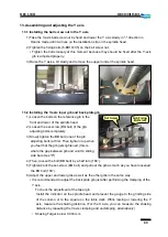
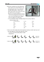
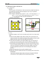
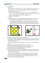
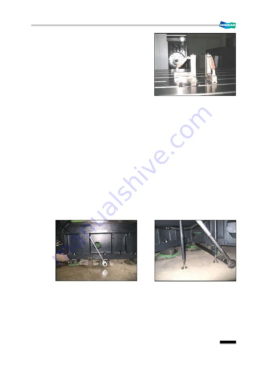
3) Place the completed level in the center of the
table deck in the X and Z directions. Then, feed
the X axis to the coordinates of "X0, X750.,
X1500., X2250., X3000." in five distinct steps.
Adjust the level block bolt to set the leveling
roughly. (set the leveling for both X and Z axes
to 0.04/m)
▪
It is recommended to make coordinate settings for the leveling in advance.
※
Setting example) O 001;
G90 G00 G54 X0.; X2250.; X1500;
M01; M01; M01;
X750.; X3000.; X750.;
M01; M01; M01
X1500.; X2250.; M99;
M01; M01.;
※
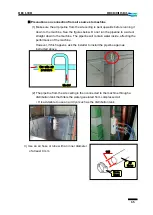
Precautions for the leveling work
①
Apply force as evenly as possible to each level block adjusting bolt so that the level
blocks contact on the bed evenly.
▪
If any one of the level blocks contacts on the bed unevenly, it may cause an
incorrect leveling in the end.
②
The last step of the leveling should be ended in the direction that the level block is
placed up (i.e., the level block adjusting bolt stops CCW).
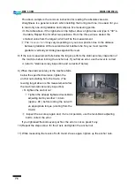
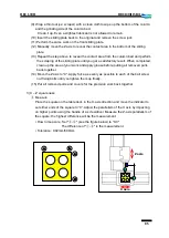
4) When the X axis is leveled roughly, move it to the center (X1050.). Then, place the level
vertically on the grinding side of the column using the magnet and set the level to "0".
Summary of Contents for DBC 130 II
Page 1: ...Installation Manual DBC 130Ⅱ Machine Tools ...
Page 2: ......
Page 7: ...5 DBC 130II DBC130II ISE41 Ref 2 Right View Ref 3 Top View ...
Page 9: ...7 DBC 130II DBC130II ISE41 Ref 6 Top view of machine to install semi splash guard on Optional ...
Page 10: ...8 DBC 130II DBC130II ISE41 Ref 7 Top view of machine to install APC on Optional ...
Page 12: ...10 DBC 130II DBC130II ISE41 60 Tool Magazine ...
Page 60: ...58 DBC 130II DBC130II ISE41 Z axis ...
Page 121: ...119 DBC 130II DBC130II ISE41 19 Installation Complete ...


