80
DBC 130II
DBC130II ISE41
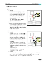
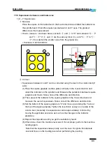
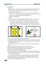
15.2 Straightness of X Axis
1) X - Y
2) Y - Z
ⓐ
Measure
Install the level in the center of the table
deck in the X- and Z-axis directions and
position it so that you can read the level
gradation. Feed the X axis in 3-divided
stroke and check the greatest difference of
the level changes.
▪
Measuring point
: X0., X1500. (X2000.), X3000. (X4000.)
▪
Tolerance: 0.030mm / full stroke
ⓑ
Correct
Incorrectness of the X-axis straightness is
thought to be attributed to an error in the
machine feeding level. So refer to "Machine
Leveling" later in this manual and perform
the leveling again.
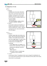
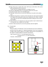
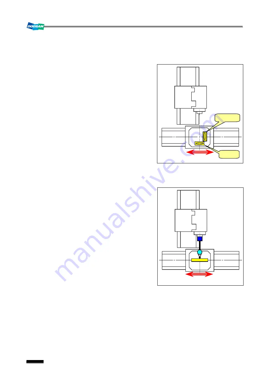
3) X - Z
ⓐ
Measure
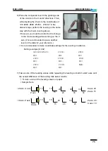
Install the straight edge horizontally on the
pallet in the X-axis direction and install the
indicator on the spindle head. Set either
end of the straight edge to “0” and move the
X axis to check the greatest difference
(measurement in the middle of the
movement).
※
If the straight edge is not available, use
the sides of the square that is required for
measuring the squareness between X
and Y axes.
▪
Measuring point
: both ends and center of straight edge
▪
Tolerance: 0.01mm / 500mm
ⓑ
Correct
Incorrectness of the X-Y straightness of the X axis is thought to be attributed to an
error in the machine feeding level. So refer to "Machine Leveling" later in this manual
and perform the leveling again.
Y-Z
X axis
X-Y
X axis
Summary of Contents for DBC 130 II
Page 1: ...Installation Manual DBC 130Ⅱ Machine Tools ...
Page 2: ......
Page 7: ...5 DBC 130II DBC130II ISE41 Ref 2 Right View Ref 3 Top View ...
Page 9: ...7 DBC 130II DBC130II ISE41 Ref 6 Top view of machine to install semi splash guard on Optional ...
Page 10: ...8 DBC 130II DBC130II ISE41 Ref 7 Top view of machine to install APC on Optional ...
Page 12: ...10 DBC 130II DBC130II ISE41 60 Tool Magazine ...
Page 60: ...58 DBC 130II DBC130II ISE41 Z axis ...
Page 121: ...119 DBC 130II DBC130II ISE41 19 Installation Complete ...

