87
DBC 130II
DBC130II ISE41
▪
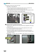
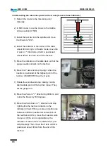
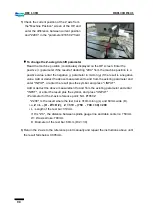
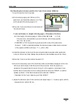
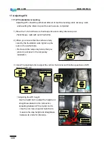
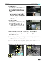
To perform the scraping of the table base sliding plate
☞
Preparations: Scraper, whetstone, minium, screw jacks (x2), cloth, other repair tools
(1) Unplug the cable that supplies power to the lubricant motor from the electric cabinet
to block lubricant inflow.
※
Turn off the power and unplug the secondary U51 and V51 wires from the terminal
block.
(2) Remove the sliding covers in either sides of the X axis.
(3) Loosen the X-axis ball screw nut fixing bolts in the side of the table base.
(4) Remove the wiper plates in either sides of the table base.
(5) Remove the back plate from the table base.
(6) Install two screw jacks on the lubricant passage in the side of the table bed, one for
each back plate place in the rear table base. Then, lift up the table base slide plate so
that you can remove it.
※
Insert a thin metal plate between screw jack and back plate to prevent scratches.
(7) Insert the bolt (BB 12×100) in the middle of the sliding plate and use the bolt as a
handle to remove the sliding plate from under the table base.
(8) Clean up the sliding plate and apply minium.
(9) Wrap a thin tool (ex: scraper) with a clean cloth to wipe up the bottom and the
grinding side of the table base.
※
Clean it up. Even a slightest lubricant is not allowed to remain.
(10) Insert the sliding plate back to the original and remove the screw jack.
(11) Perform the same work on the other sliding plate.
(12) Manually move the X axis to reveal the contact area in the bottom of the sliding
plate.
(13) Check the contact state on the table base and keep scraping the sliding plate until
you get a satisfactory result.
(14) When you get a satisfactory result, clean up the working area and apply lubricant,
then put together all the removed component parts back to the original.
(15) Move the X axis to “0”. Apply force as evenly as possible to each of the ball screw
nut fixing bolts until you tighten them up finally.
(16) Put all removed parts and covers for the precision work back together.
Summary of Contents for DBC 130 II
Page 1: ...Installation Manual DBC 130Ⅱ Machine Tools ...
Page 2: ......
Page 7: ...5 DBC 130II DBC130II ISE41 Ref 2 Right View Ref 3 Top View ...
Page 9: ...7 DBC 130II DBC130II ISE41 Ref 6 Top view of machine to install semi splash guard on Optional ...
Page 10: ...8 DBC 130II DBC130II ISE41 Ref 7 Top view of machine to install APC on Optional ...
Page 12: ...10 DBC 130II DBC130II ISE41 60 Tool Magazine ...
Page 60: ...58 DBC 130II DBC130II ISE41 Z axis ...
Page 121: ...119 DBC 130II DBC130II ISE41 19 Installation Complete ...


