OP000506
1-45
Safety
Disconnect Batteries Before Electrical
Service or Electrical Welding
Remove cable to negative terminal first when disconnecting
cable. Connect positive terminal cables first when installing a
battery.
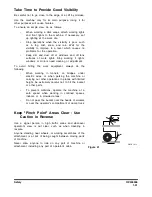
Use Low Heat Portable Lighting
Hot surfaces on trouble lights or portable work lights can set
off fuel or battery explosive gases.
Boost Starting or Charging Engine
Batteries
If any mistake is made in the method of connecting the
booster cables, it may cause an explosion or fire. Always do
the following:
•
Turn off all electrical equipment before connecting
leads to the battery. This includes electrical
switches on the battery charger or boost starting
equipment.
•
When boost starting from another machine or
vehicle do not allow the two machines to touch.
Wear safety glasses or goggles while required
battery connections are made.
•
24 volt battery units consisting of two series
connected twelve volt batteries have a cable
connecting one positive terminal on one of the 12
volt batteries to a negative terminal on the other
battery. Booster or charger cable connections
must be made between the nonseries connected
positive terminals and between the negative
terminal of the booster battery and the metal
frame of the machine being boosted or charged.
Refer to the procedure and illustration in “Starting
with Auxiliary Batteries” on page 3-8 of this
manual.
•
Connect positive cable first when installing cables
and disconnect the negative cable first when
removing them. The final cable connection, at the
metal frame of the machine being charged or
boost started, must be as far away from the
batteries as possible.
Figure 38
HAOA310L
Summary of Contents for DL200
Page 2: ......
Page 6: ...K1024537E Table of Contents IV ...
Page 7: ...K1024537E I I Presentation 1Presentation PRESENTATION FG008047 Figure 1 ...
Page 17: ...OP000506 1 5 Safety 1 3 10 12 6 4 11 5 9 8 3 7 10 9 4 6 2 FG008049 Figure 1 ...
Page 60: ...OP000506 Safety 1 48 ...
Page 112: ...OP000507 Operating Controls 2 52 CD Player Optional AST DIR FG000109 Figure 101 ...
Page 122: ...OP000507 Operating Controls 2 62 ...
Page 232: ...OP000509 Inspection Maintenance and Adjustment 4 88 ...
Page 242: ...OP000040 Troubleshooting 6 8 ...
Page 252: ...OP000510 Specification 7 10 ...

