OP000509
4-25
Inspection, Maintenance and Adjustment
Check Hydraulic System Oil Level
1.
Move machine to a level area and shut down engine.
2.
Apply parking brake.
3.
Lower bucket to ground.
4.
Check sight gauge that is attached to hydraulic tank.
Oil level must be visible in red centered circle shown
on sight gauge (1, Figure 19).
5.
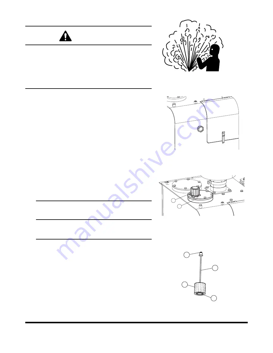
To add hydraulic oil, turn breather cap (1, Figure 20)
slowly to allow pressurized air to vent.
6.
Remove upper cover (2, Figure 20) from hydraulic oil
tank and raise boom at max. height and replenish oil
to the top of sight gauge (Figure 19).
The hydraulic oil fill cover also serves as the hydraulic oil
strainer access cover. It is important to replace this cover
and the components in the proper order and alignment.
The filter (2, Figure 21), retaining rod (3) and spring (4) are
assembled as shown in Figure 21. The hole (1) in the base
of the filter fits over a circular base in the bottom of the
tank. The retaining rod (3) screws into the top of the filter
(2), but the spring (4) slides over the top of the rod. Be
certain that this spring does not fall into the tank during
reassembly.
1.
If filter assembly was removed, insert assembly into the
tank and check to make sure it is securely in place.
Figure 18
HAOA060L
WARNING!
The hydraulic oil will be hot after normal machine
operation. Allow system to cool before attempting to
service any of the hydraulic components.
The hydraulic tank is pressurized. Turn breather cap
slowly to allow pressurized air to vent. After the
pressure has been released, it is safe to remove either
the fill cap or service covers.
FG008086
Figure 19
1
2
FG008087
Figure 20
IMPORTANT
Do not fill above red centered circle on sight gauge.
Overfilling can result in damage to equipment and
oil leaking from hydraulic tank due to expansion.
3
4
2
1
FG002188
Figure 21
Summary of Contents for DL200
Page 2: ......
Page 6: ...K1024537E Table of Contents IV ...
Page 7: ...K1024537E I I Presentation 1Presentation PRESENTATION FG008047 Figure 1 ...
Page 17: ...OP000506 1 5 Safety 1 3 10 12 6 4 11 5 9 8 3 7 10 9 4 6 2 FG008049 Figure 1 ...
Page 60: ...OP000506 Safety 1 48 ...
Page 112: ...OP000507 Operating Controls 2 52 CD Player Optional AST DIR FG000109 Figure 101 ...
Page 122: ...OP000507 Operating Controls 2 62 ...
Page 232: ...OP000509 Inspection Maintenance and Adjustment 4 88 ...
Page 242: ...OP000040 Troubleshooting 6 8 ...
Page 252: ...OP000510 Specification 7 10 ...


