OP000598
3-37
Operation
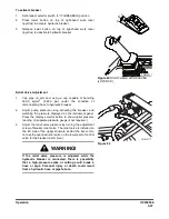
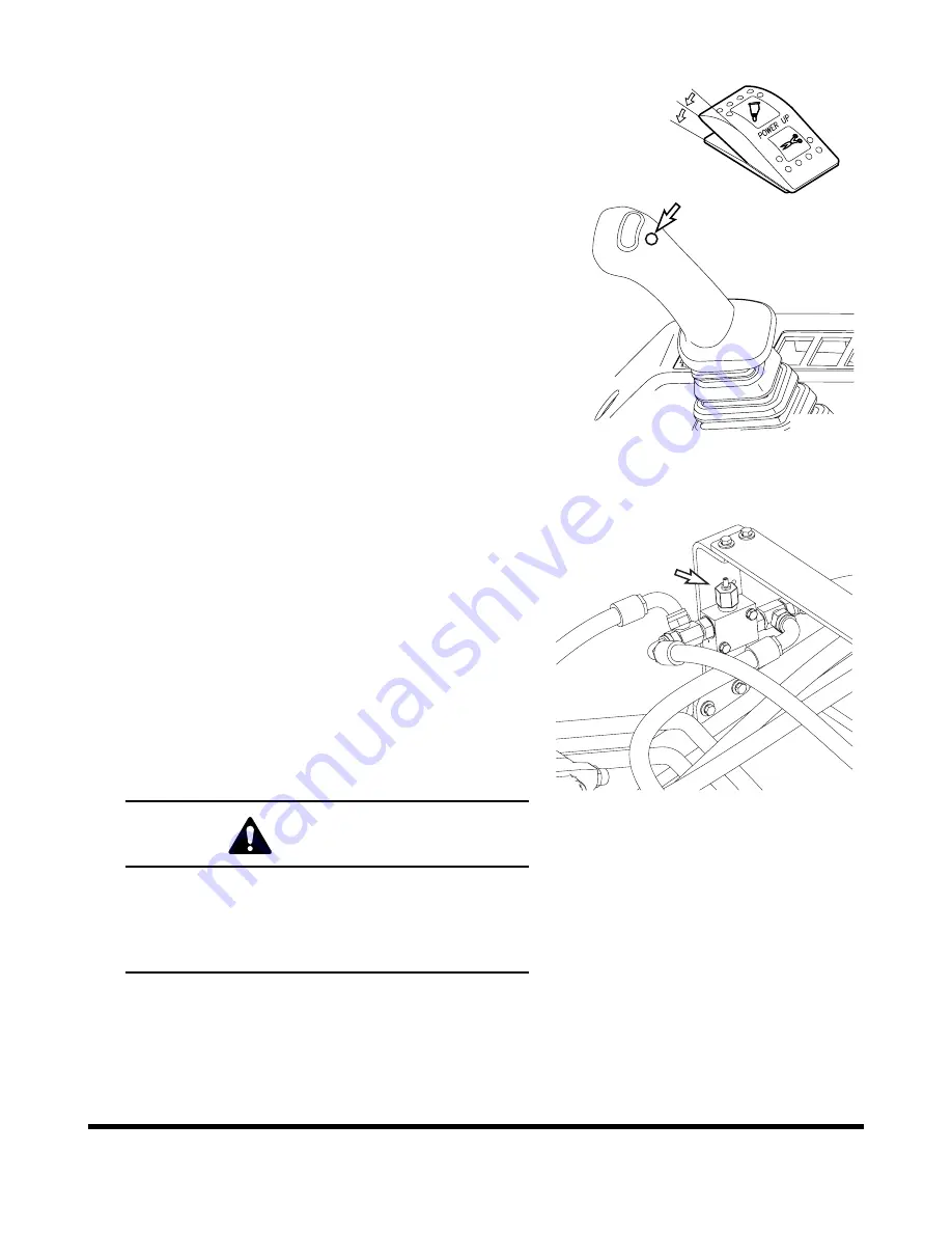
To activate breaker
1.
Set breaker selector switch to "II" (BREAKER) position.
2.
Press lower button on top of right-hand work lever
(joystick) to activate hydraulic breaker.
3.
Release lower button on top of right-hand work lever
(joystick) to deactivate hydraulic breaker.
Relief Valve Adjustment
1.
Cap pipe on arm end, using a cap capable of handling
350.0 kg/cm
2
(5,000 psi) under the condition of
disconnecting hose to hydraulic breaker.
2.
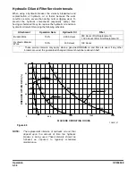
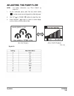
Adjust pump pressure using activating the breaker, and
watching the pressure displayed on the instrument panel.
Press the display selector button to show digital pressure
reading. (A separate pressure gauge is not required.)
3.
Adjust the relief valve pressure by turning the adjustment
screw of breaker relief valve. The relief valve is installed on
the left side of the upper structure behind the boom. (Do
not use the overload relief valve on the lower part of control
valve for the breaker relief valve.)
FG000117
O
I
I
I
Figure 83
RIGHT-HAND WORK LEVER
(JOYSTICK)
FG000777
Figure 84
WARNING!
If the relief valve pressure is adjusted while the
hydraulic breaker is connected, there is possibility
that a high-pressure spike or setting could break a
hose or pipe. Personal injury or death could result
from a hydraulic hose or pipe failure.
Summary of Contents for DX140LC
Page 2: ......
Page 67: ...OP000597 2 3 Operating Controls ...
Page 87: ...OP000597 2 23 Operating Controls ...
Page 122: ...OP000597 Operating Controls 2 58 CD Player Optional AST DIR FG000109 Figure 123 ...
Page 184: ...OP000598 Operation 3 48 ...
Page 193: ...OP000599 4 9 Inspection Maintenance and Adjustment ...
Page 272: ...OP000599 Inspection Maintenance and Adjustment 4 88 ...
Page 278: ...OP000600 Transportation 5 6 ...
Page 284: ...OP000013 Troubleshooting 6 6 ...
Page 292: ...OP000601 Specification 7 8 ...

