OP000597
Operating Controls
2-10
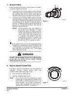
1. Starter Switch
A three-position starter switch is used to start or shut down
engine for equipment operation.
O.
Turning the switch to this position turns the engine
"OFF" along with its electrical system. In this position
the engine is "OFF" but the interior cabin light and
fuel tank transfer pump (if equipped) are functional.
I.
Turning the switch to this position turns the engine
electrical system "ON." When the switch is first turned
"ON" the six indicator/warning lights across the top of
the instrument panel, will light for approximately two
seconds. The battery warning light and the engine oil
pressure warning light should remain "ON" after the
other four have turned "OFF."
NOTE:
Preheat Indicator Light - The operation of
the preheat cycle depends on coolant
temperature. When the engine coolant is
cold enough, the preheat indicator light will
remain "ON" until the engine preheat cycle
is completed. The preheat cycle takes
about twenty seconds to complete, and
the indicator light will turn "OFF." When
the light turns "OFF," engage the starter.
. Moving switch to this position will crank engine. When
engine starts, release key and allow it to return to the
"I" (ON) position. Do not operate the starter switch for
more than fifteen seconds at a time. This will help
prevent damage to starter.
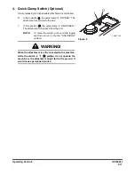
2. Engine Speed Control Dial
The engine speed is controlled by the dial. Rotating it
clockwise increases engine speed (rpm) and
counterclockwise decreases engine speed.
A
Low idle (Lowest engine speed)
B
High idle (Highest engine speed)
NOTE:
The auto idle system will automatically reduce
engine speed to idle speed approximately four
seconds after all of the control levers are in the
neutral position. This system is designed to
reduce fuel consumption and noise. See “3.
Auto Idle Selector Button” on page 2-37.
FG000014
O
I
Figure 4
WARNING!
DO NOT USE STARTING FLUIDS. The preheat system
could cause the starting fluid to explode. Starting
fluids should never be used.
HAOA690L
Figure 5
Summary of Contents for DX140LC
Page 2: ......
Page 67: ...OP000597 2 3 Operating Controls ...
Page 87: ...OP000597 2 23 Operating Controls ...
Page 122: ...OP000597 Operating Controls 2 58 CD Player Optional AST DIR FG000109 Figure 123 ...
Page 184: ...OP000598 Operation 3 48 ...
Page 193: ...OP000599 4 9 Inspection Maintenance and Adjustment ...
Page 272: ...OP000599 Inspection Maintenance and Adjustment 4 88 ...
Page 278: ...OP000600 Transportation 5 6 ...
Page 284: ...OP000013 Troubleshooting 6 6 ...
Page 292: ...OP000601 Specification 7 8 ...

