1-39
DX380LC-7
•
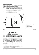
Visible areas with rear CCTV and mirrors
•
Visible areas with side/rear CCTV and mirrors
•
Machine travel position
–
A is 5.1 m (16' 9") from swing center to bucket pin
–
B is 5.7 m (18' 8") from ground to arm pin
Mirror Adjustment
Frequently ensure the mirrors are directed properly.
•
Park the machine on a level surface.
•
Lower the attachment to the ground.
•
Lower the safety lever to the LOCK position.
•
Stop the engine.
•
Use the machine access system.
NOTE:
You may need hand tools to adjust certain types of
mirrors.
12 m (
472 in)
F
W
D
DS2100287
Figure 29
12 m (
472 in)
F
W
D
DS2100288
Figure 30
DS1801218
A
B
Figure 31

