G80XW/XF, G115XW/XF, G150XW/XF, G200XW/XF - 50HZ
OPERATION & MAINTENANCE MANUAL
97
G100XW/XF, G135 XW/XF, G170XW/XF, G225XW/XF - 60Hz
INSTALLATION
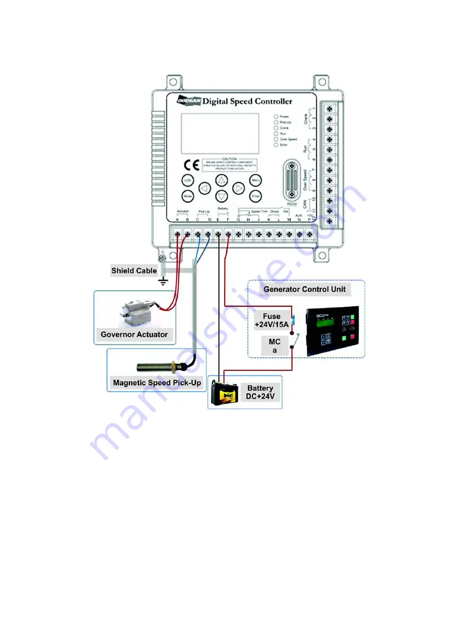
Connecting to the Engine Battery,
Pick-Up and Actuator Connection Diagram
Connecting to Batteries
Battery voltage is DC +24Vand the battery is connected
to the controller matching
E(-)
and
F(+)
with the
respective polarities of the battery.
E(-)
is connected to
(-)
of the battery and
F(+)
to
(+)
of the battery. Depending on
cases, wiring can be done in a serial connection to the
contact point a of MC and the fuse (DC +24V/15A) when
connecting to system panels or generator control
devices.
Connecting to Actuators
The actuator is also called governor and controls the
amount of the fuel spray to the engine cylinder. The
controller is connected to the actuator attached on the
engine by connecting two wires of the controller terminal
to A and B of the actuator regardless of their polarities.
Wiring should be 18AWG (105?) or better and the outside
should be wrapped by plastic tubes for insulation or
insulated mesh lines.
Connecting to Pick-Up Sensors
The pick-up sensor lets users know the engine speed
and is connected to terminals C and D that can receive
signals of AC RMS 3Vor higher. Wiring should be twisted,
or shielded cables connected to the ground together with
the terminal D. Gap between the pick-up sensor and the
gear tooth should be adjusted between 0.9 and 1.1mm.


