67
4.2.3
Setting the Digital I/O Power Terminal (TBPWR)
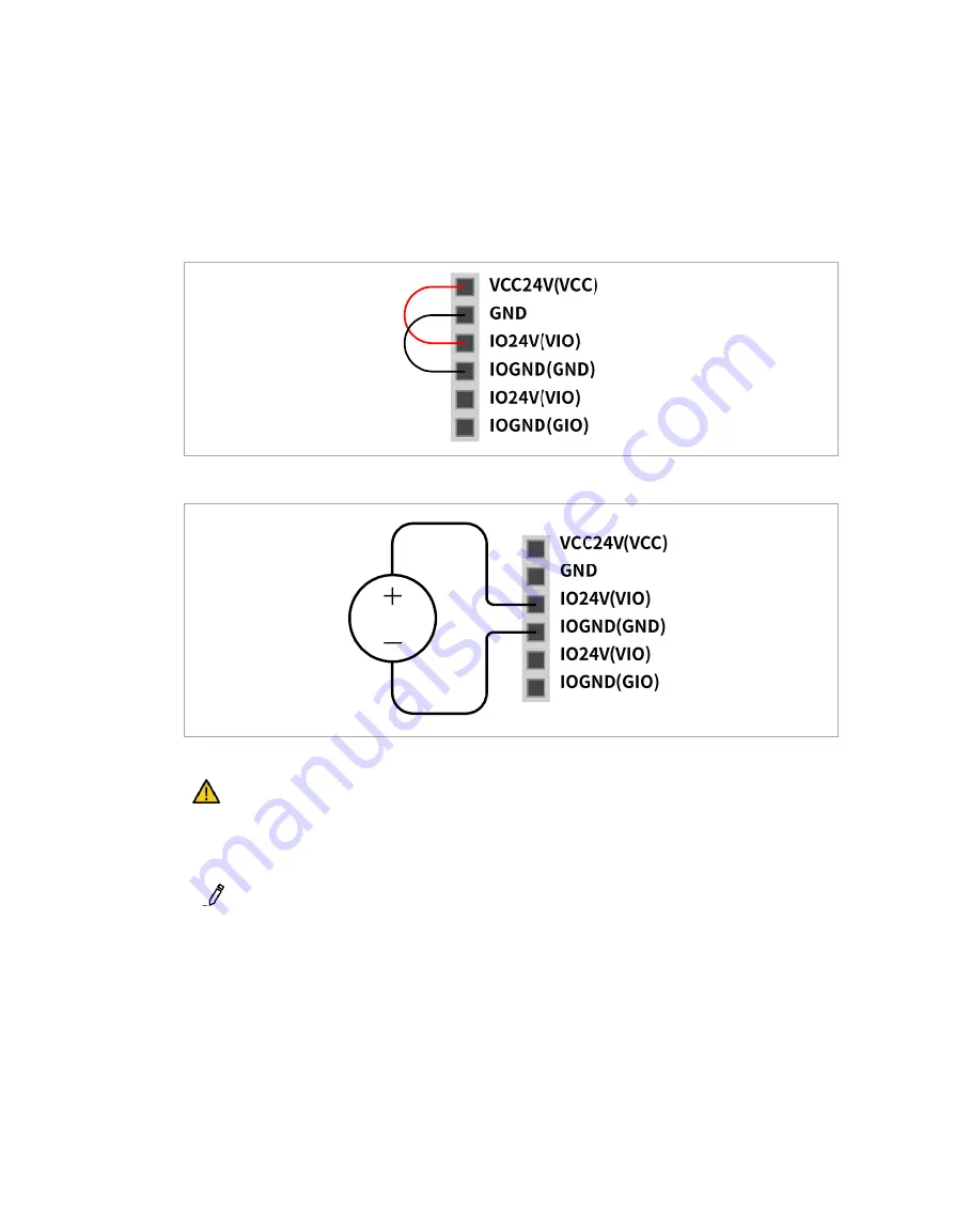
VIO and GIO are power terminals used for the safety controller digital I/O located in the front of the
controller, and they are separated from the VCC24V and GND, which supply SMPS inside the
controller. If the user uses a current of 2A or less for the configurable digital I/O, and if there is no
insulation for the connected I/O device and controller, the internal power supply of the controller can be
used as the I/O power supply, as shown in the figure below. (factory default setting)
If a current greater than 2A is required, it is necessary to connect a separate external power source
(24V) using VIO and GIO.
The IOPW (green) LED located on top of the TBPWR lights on if VIO power is supplied.
Caution
Make sure to turn off the external power source (SMPS) when turning off the power for the
controller.
Note
If a current greater than 2A is used by the connected VCC and GND of TBPWR, the fuse in
front of the terminal power output shorts to ensure the safety of the controller internal system
connected to the same SMPS.
If a current greater than 2A is required for the configurable digital I/O, make sure to connect an
external power source (24V) to VIO and GIO.
Summary of Contents for H2017
Page 1: ...1 Manual Version 2 1 Software Version 2 7 1 ...
Page 29: ...29 2 5 3 Robot operating space M0609 ...
Page 30: ...Doosan Robotics Installation Manual v2 1 30 ...
Page 31: ...31 M0617 ...
Page 32: ...Doosan Robotics Installation Manual v2 1 32 ...
Page 33: ...33 M1013 ...
Page 34: ...Doosan Robotics Installation Manual v2 1 34 ...
Page 35: ...35 M1509 ...
Page 36: ...Doosan Robotics Installation Manual v2 1 36 ...
Page 37: ...37 H2017 ...
Page 38: ...Doosan Robotics Installation Manual v2 1 38 ...
Page 39: ...39 H2515 ...
Page 40: ...Doosan Robotics Installation Manual v2 1 40 ...
Page 42: ...Doosan Robotics Installation Manual v2 1 42 M1013 M1509 ...
Page 119: ...119 B 2 Europe Machinery Directive Attestation of Conformity ...
Page 120: ...Doosan Robotics Installation Manual v2 1 120 ...
Page 121: ...121 B 3 Europe EMC Directive Attestation of Conformity ...
Page 122: ...Doosan Robotics Installation Manual v2 1 122 B 4 U S NRTL Certification U S CANADA ...
Page 123: ...123 ...
Page 124: ...Doosan Robotics Installation Manual v2 1 124 B 5 Functional Safety Certification ...
Page 125: ...125 B 6 Voluntary Safety Confirmation Declaration KCs ...
Page 126: ...Doosan Robotics Installation Manual v2 1 126 ...
Page 127: ...127 ...
Page 128: ...Doosan Robotics Installation Manual v2 1 128 ...
Page 129: ...129 ...
Page 130: ...Doosan Robotics Installation Manual v2 1 130 ...
Page 161: ...161 D 1 3 Nameplate and Label ...
Page 176: ...Doosan Robotics Installation Manual v2 1 176 E 1 3 Nameplate and Label ...
Page 190: ...Doosan Robotics Installation Manual v2 1 190 ...


