background image

58

OPERATION

7/20, P65

CHECKS AND OPERATION AFTER START

UP


Check after the Engine Start

up


Check the following items in the engine warming

up operation. 

Engine noise and exhaust smoke color


Listen to the engine and, if any abnormal noise is heard, check to

determine the cause. 

Check the fuel combustion condition by observing the exhaust

smoke color. The exhaust smoke color after engine warm

up and at

no

load condition should be colorless or light blue.

Black or white smoke indicates incorrect combustion.

Note: 

After start

up from cold the engine might be noisier and the

exhaust smoke color darker than when it has warmed up. However this

condition will disappear after warm up.

Leakage in the systems 


Check the following items:

Lubrication oil leakage 

Check the engine for oil leaks, paying particular attention to oil filter

and oil pipe joints.

Fuel leakage 


Check the fuel injection pump, fuel lines and fuel filter for leakage.

Coolant leakage 

  Check the radiator and water pump hose

connections and the water drain cock on the cylinder block for leakage.

Exhaust smoke or gas leakage 

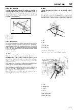
Checking coolant level


The coolant level could drop because any mixed air is expelled in about
5 minutes after the engine started. 

Stop the engine, remove radiator cap, and add coolant. 

CAUTION:

 Hot steam can rush out and you could get burnt if the

radiator cap is removed when the engine is hot. Cover the radiator cap

with a thick cloth and loosen the cap slowly to reduce the pressure, then
remove the cap. 

OPERATION AND CARE OF A NEW ENGINE

.

Your Ingersoll Rand engine is carefully tested and adjusted in the

factory, however, further run

in is necessary. Avoid any harsh engine

operation within the initial 100 operating hours.

Do not operate the unit at full load until the engine is warmed

up.

Do not allow the engine to run unloaded for extended periods so as to

minimise the risk of cylinder bore glazing.

During operation, pay attention to the following points if the engine
shows any sign of abnormalities. 

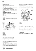
(1) Engine Oil Pressure 

 The engine oil pressure is monitored by a

switch that will stop the engine if the pressure falls below a pre

set

value.

(2) Coolant Temperature 


The engine performance will be adversely

affected if engine coolant temperature is too hot or too cold. The normal
coolant temperature is 75 to 85

C (167 to 185

F).

Overheating


CAUTION: 

If you see or hear escaping steam or have other reason to suspect
there is a serious overheat condition, stop the engine immediately.

If the Engine Coolant Temperature gage (where fitted) shows an

overheat condition, or you have reason to suspect the engine may be
overheating, take the following step: 

Close the service valve to reduce the load.  

Let the engine run at normal idle speed for two or three minutes. If

the engine coolant temperature does not start to drop, turn off the
engine and  proceed as follows: 

CAUTION: 

To help avoid being burned 


Do not open the canopy or door if you see or hear steam or engine

coolant escaping. Wait until no steam or engine coolant can be seen or
heard before opening the engine canopy or door.

Do not remove the radiator filler cap if the engine coolant in the

reserve tank is boiling. Also do not remove the radiator filler cap while

the engine and radiator are still hot. Scalding fluid and steam can be
blown out under pressure if either cap is taken off too soon. 

If no steam or engine coolant can be seen or heard, open the canopy

or door. If the engine coolant is boiling, wait until it stops before

proceeding. The engine coolant level should be between the “MAX
COLD” and “MIN” marks on the reserve tank.

Make sure the fan belt is not broken, or off the pulley, and that the fan

turns when the engine is started. If the engine coolant level in the

reserve tank is low, look for leaks at the radiator hoses and

connections, radiator, and water pump. If you find major leaks, do not

run the engine until these problems have been corrected. If you do not

find a leak or other problem, WAIT UNTIL THE ENGINE HAS COOLED
DOWN then carefully add engine coolant to the reserve tank.

(Engine coolant is a mixture of ethylene glycol antifreeze and water.

See “Engine Care in cold season” for the proper antifreeze and
mixture.)

CAUTION:

 To avoid being burned, do not spill antifreeze or engine

coolant on the exhaust system or hot engine parts. Under some
conditions the ethylene glycol in engine coolant is combustible. 

If the engine coolant level in the reserve tank is at the correct level but

there is still an indication of an overheat condition and no cause was
found, please consult your local Ingersoll Rand branch or dealer.

Overcooling


Operating the engine at low coolant temperature will not only increase

the oil and fuel consumption but also will lead to premature parts wear

which may result in engine failure. Ensure that the engine reaches

normal operating temperature 75 to 85

C (167 to 185

F) within ten

minutes of starting.

(3) Hourmeter


This meter indicates the machine operation hours. Make sure that the

meter is always working during engine operation. Periodical machine

maintenance is scheduled on the operation hours indicated on the
hourmeter. 

(4) Liquid and Exhaust Smoke Leakage


Make regular checks for lubricant, fuel, coolant and exhaust smoke
leakage.

(5) Abnormal Engine Noise


In the event of any abnormal engine noise, please consult your local
Ingersoll Rand branch or dealer. 

(6) State of the Exhaust Smoke


Check for any abnormal exhaust smoke color.

ENGINE STOPPING


(1) Close service valves.

(2) Before stopping the engine, cool down the engine by operating it at

reduced load about three minutes. In this period, check the engine

noise for abnormalities.

Summary of Contents for Ingersoll Rand 7/20

Page 1: ...121001 SERIAL No Revised 10 12 Doosan purchased Bobcat Company from Ingersoll Rand Company in 2007 Any reference to Ingersoll Rand Company or use of trademarks service marks logos or other proprietary...

Page 2: ...hat the machine display the CE Mark and conform to various directives In such cases the design specification of this machine has been certified as complying with EC directives Any modification to any...

Page 3: ......

Page 4: ...CALIFORNIA Proposition 65 Warning Diesel engine exhaust and some of its constituents are known to the State of California to cause cancer birth defects and other reproductive harm...

Page 5: ...ectrical system Piping instrumentation system 46 FAULT FINDING 48 OPTIONS Lubricator Safety General Information Operating Instructions Maintenance Fault Finding 49 ENGINE INSTRUCTION MANUAL ABBREVIATI...

Page 6: ...oll Rand has no control Therefore Ingersoll Rand cannot be held responsible for equipment in which non approvedrepair parts are installed Ingersoll Rand reserves the right to make changes and improvem...

Page 7: ...rsoll Rand Engine and Airend combination The earlier of sixty 60 months from shipment to or the accumulation of 10 000 hours of operationby the initial user The starter alternator fuel injection syste...

Page 8: ...2 MONTHS 2 000 HOURS EXTENDED WARRANTY OF 24 MONTHS 4 000 HRS FOR LIGHTSOURCE INTRODUCED 8 16 99 ENGINE SEE BELOW ENGINES MONTHS HOURS COMMENTS CATERPILLAR 12 UNLIMITED EXTENDED WARRANTY PROVIDED VIA...

Page 9: ...RANTY PROVIDED VIA ENGINE SUPPLIERS S OWN APPROVED NETWORK VANGUARD 24 UNLIMITED WARRANTY PROVIDED VIA ENGINE SUPPLIERS S OWN APPROVED NETWORK PARTS MONTHS HOURS COMMENTS INGERSOLL RAND 6 UNLIMITED PA...

Page 10: ...in major components rotors housings gears and bearings and is automatically available when the following conditions are met 1 The original airend is returned assembled and unopened 2 Submissions of pr...

Page 11: ...oosanwarranty dii doosan com Note Completion of this form validates the warranty Engine Registration I R powered machines do not require separate engine registration Deutz require a separate engine re...

Page 12: ...records and mail form to Doosan International USA Inc 1293 Glenway Drive Statesville North Carolina 28625 9218 Attn Warranty Department Note Completion of this form validates the warranty Engine Regis...

Page 13: ...r Details Company Name Service Provider Distributor Contact Name Branch Office Signature Company Address Machine Details Product Type Model Serial Number Engine Serial Number Engine Model Number Post...

Page 14: ...orrosion risk WARNING Air gas flow or Air discharge WARNING Pressurised vessel WARNING Hot and harmful exhaust gas WARNING Flammable liquid X XBAR 0 C WARNING Maintain correct tyre pressure Refer to t...

Page 15: ...remove the Operating and Maintenance manual and manual holder from this machine Do not stack Do not operate the machine without the guard being fitted Do not stand on any service valve or other parts...

Page 16: ...e manual before operation or maintenance of this machine is undertaken When parking use prop stand handbrake and wheel chocks Compressor oil filling Diesel fuel No open flame Parking brake Rough Servi...

Page 17: ...y damage if ignored CAUTION Yellow background Indicates the presence of a hazard which WILL or can cause injury or property damage if ignored NOTICE Blue background Indicates important set up operatin...

Page 18: ...ous injury or death When using air tools attach safety device OSHA Valve at source of air supply for each tool WARNING High pressure air Can cause serious injury or death Relieve pressure before remov...

Page 19: ...or Non Highway Towable Machines Safety Decals are available free of charge Safety decals are identified by the decal heading DANGER WARNING or CAUTION Decal part numbers are on the bottom of each deca...

Page 20: ...ake system or parts thereof c enclosure or parts thereof 2 Removal of any of the following a fan shroud b vibration mounts c sound absorption material 3 Operation of the compressor with any of the enc...

Page 21: ...noise control prior to its sale or delivery to the ultimate purchaser or while it is in use or 2 the use of the compressor after such a device or element of design has been removed or rendered inoper...

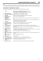
Page 22: ...purchaser or owner can record what maintenance was done by whom where and when Detailed instructions on the maintenance items below are given on the following page MAINTENANCE SCHEDULE ITEM AREA PERI...

Page 23: ...oise containment function is reduced should be repaired or replaced before the next operation interval Doors access panels and hatch closures especially should be checked and adjusted at this time to...

Page 24: ...ISSION CONTROL AND EXTENDED WARRANTY 20 7 20 P65 MAINTENANCE RECORD FOR NOISE EMISSION CONTROL AND EXTENDED WARRANTY ITEM NO DESCRIPTION OF WORK OR COMMENTS HOURMETER READING MAINT INSPECT DATE LOCATI...

Page 25: ...air to prevent debris from injuring eye s Rotating fan blade can cause serious injury Do not operate without guard in place Use care to avoid contacting hot surfaces engine exhaust manifold and pipin...

Page 26: ...ect ends of one booster cable to the positive terminal of each battery Connect one end of other cable to the negative terminal of the booster battery and other end to a ground connection away from dea...

Page 27: ...hout the handbrake being applied Where brakes and safety chains are fitted a Loop the chains onto the towing vehicle using the towing vehicle hitch as an anchorage point or any other point of similar...

Page 28: ...GENERAL INFORMATION 24 7 20 P65 7 20 VARIABLE HEIGHT RUNNING GEAR 7 20 FIXED HEIGHT RUNNING GEAR...

Page 29: ...nt supplier For temperatures outside the specified ambient range consult Ingersoll Rand ENGINE 7 20 P65 Type model 7 20 D1005 EBB EC L T 1 P65 D1005 E3B IRCZ Number of cylinders 3 Oil capacity 5 1 lit...

Page 30: ...s ensure that the lights are functioning correctly where fitted Ensure that all transport and packing materials are discarded Ensure that the correct fork lift truck slots or marked lifting tie down p...

Page 31: ...m occurring in the tank CAUTION Use only a No 2 D diesel fuel oil with a minimum octane number of 45 and a sulphur content not greater than 0 5 CAUTION When refueling switch off the engine do not smok...

Page 32: ...eriod of time to reduce the engine temperature Turn the start switch to the 0 off position NOTE As soon as the engine stops the automatic blowdown valve will relieve all pressure from the system If th...

Page 33: ...articular Do not destroy batteries or components containing asbestos without containing the materials safely Do not dispose of any pressure vessel that is not clearly marked with its relevant data pla...

Page 34: ...Connections Electrolyte C Tire Pressure and Surface C Wheel Lug Nuts C Hoses Oil Air Intake etc C Automatic Shutdown System C Air Cleaner System C Compressor Oil Cooler Exterior C Engine Rad Oil Coole...

Page 35: ...lement R Feed Pump Strainer Cleaning C Coolant Replacement R Valve Clearance Check C Lights running brake turn CBT Pintle Eye Bolts CBT Brakes C C Brake linkage C Emergency stop T Fasteners C Running...

Page 36: ...2 Years 2 Yrs 4 Yrs 6 Yrs Airend drive belt R Safety valve C Hoses R Separator tank 2 interior C Disregard if not appropriate for this particular machine 1 or 3000 miles 5000km whichever is the sooner...

Page 37: ...carried out with safety protection devices disabled or removed is limited to only those tasks which require the machine to be running with safety protection devices disabled or removed all hazards pr...

Page 38: ...ion of this manual and check for leakage before the machine is put back into service COMPRESSOR OIL SEPARATOR ELEMENT Normally the separator element will not require periodic maintenanceprovided that...

Page 39: ...nlets and outlets are clear of debris etc CAUTION NEVER clean by blowing air inwards COOLING FAN DRIVE Periodically check that the fan mounting bolts in the fan hub have not loosened If for any reason...

Page 40: ...6 Breakaway Cable Requirements During the adjustment procedure always start with the wheel brakes Always rotate the wheel in the direction of forward movement Ensure that an M10 safety screw is fitted...

Page 41: ...ake linings must not be corrected by re adjusting shortening the brake linkage 7 Re adjustment The handbrake lever 1 should be engaged forcefully several times to set the braking system Check the sett...

Page 42: ...RE REGULATION ADJUSTMENT Normally regulation requires no adjusting but if correct adjustment is lost proceed as follows Refer to the diagram above A Throttle arm B Adjusting screw Start the machine Re...

Page 43: ...adjusting screw and pivot Airend towards engine to slacken belt and remove belt from pulleys Fit new belt over pulleys pivot Airend away from engine and re engage adjusting screw Adjust drive belt tig...

Page 44: ...lamp on discharge hose 58 67 78 91 Exhaust flange to manifold 17 21 23 28 Fan guard 9 11 12 15 Fan to hub 12 15 16 20 ft lbf Nm Lifting bail to frame 29 35 39 47 Band clamp on oil pipes 71 88 96 119 R...

Page 45: ...C to 18 C IR XHP 505 IR XHP1001 IR Performance 500 Mil L 46167 34 5bar 500 psi 50 F to 125 F 10 C to 52 C 10 F to 65 F 12 C to 18 C below 10 F 12 C IR XHP1001 IR XHP 505 Consult Factory IR XHP505 IR X...

Page 46: ...Diode blocking FP Fuel pump G Alternator GP Glowplugs h Hourmeter M Starter motor NP1 4 Node point PS1 Engine oil pressure switch RT1 Relay temperature switch SO Key switch SV1 Solenoid fuel TS1 High...

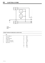
Page 47: ...STEM 43 7 20 P65 SCHEMATIC DIAGRAM FOR EUROPEAN CE LIGHTING SYSTEM KEY 1 Plug 2 Light right hand 3 Fog light 4 Light left hand B Black G Green K Pink N Brown O Orange P Purple R Red S Grey U Blue W Wh...

Page 48: ...E LIGHTING SYSTEM KEY 1 Stop turn left hand 2 Tail left hand 3 Stop turn right hand 4 Tail right hand 5 Front side marker left hand 6 Front side marker right hand 7 Ground earth B Black G Green K Pink...

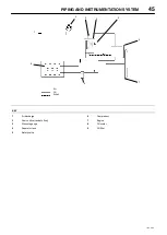
Page 49: ...INSTRUMENTATION SYSTEM 7 20 P65 Air Oil Air oil 1 2 3 8 4 5 6 7 9 KEY 1 Air discharge 2 Sonic orifice restricts flow 3 Pressure gauge 4 Separator tank 5 Safety valve 6 Compressor 7 Engine 8 Oil cooler...

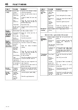
Page 50: ...e if necessary Engine Overheats Reduced cooling air from fan Check the fan and the drive belts Check for any obstruction inside the cowl Engine speed too high Incorrect throttle arm setting Check the...

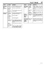
Page 51: ...ctions Check all pipe hose connections Faulty safety valve Check the relieving pressure Replace the safety valve if faulty DO NOT ATTEMPT A REPAIR FAULT CAUSE REMEDY Oil is forced back into the air fi...

Page 52: ...FAULT CAUSE REMEDY No oil flow Incorrect connection Reverse the nylon tube connections to the lubricator BUNDED BASE Description This machine can be fitted with bund equipment to contain leakages and...

Page 53: ...and engine after sales support EMISSION CONTROL LABEL 54 FUEL LUBRICANT AND COOLANT Fuel Lubricant Coolant 56 OPERATION Check before operation Check and operation after start up Operation and care of...

Page 54: ...orrectly This Manual is designed to help you do this Please read this Manual carefully and follow its operating and maintenance recommendations This will ensure many years of trouble free and economic...

Page 55: ...4 Oil level gauge 15 Oil pressure switch 16 Flywheel 17 Oil drain plug 18 Oil pan 19 Engine hook 1 2 3 4 5 6 7 8 9 10 11 12 13 14 15 16 17 18 19 1 Intake manifold 2 Speed control lever 3 Engine stop l...

Page 56: ...cold mm 0 145 0 185 Nozzle injection pressure MPa 13 73 Injection timing B T D C at 2 5mm cam lift 19 ENGINE IDENTIFICATION Serial No Location See illustration on page 53 Confirmation of Engine Number...

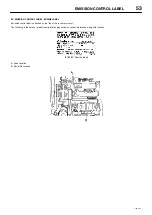
Page 57: ...BEL ENGINE LABEL Emission control label is attached on the top of the rocker arm cover The following is the detail of a label required for engine emission control information along with location 97 68...

Page 58: ...either may cause engine damage Handling of the Fuel Any fuel containing dust particles or water might cause engine failure Therefore the following must be observed Take care to protect the fuel from...

Page 59: ...gine damage due to improper maintenance or using oil of the improper quality and or viscosity is not covered by the warranty Fig 12 A Single grade B Ambient Temperature C Multi grade COOLANT All Inger...

Page 60: ...il filler to the crankcase Wait at least ten minutes before checking the oil level NOTE Take care to avoid engine oil being splashed on the fan drive belt because it causes belt slippage or slackness...

Page 61: ...d is used as electrolyte be careful not to contaminateyour eyes hands clothes and metals with the electrolyte If it gets in your eye wash with a large amount of water at once then seek medical advice...

Page 62: ...l idle speed for two or three minutes If the engine coolant temperature does not start to drop turn off the engine and proceed as follows CAUTION To help avoid being burned Do not open the canopy or d...

Page 63: ...ce per week and run on load for about 15 minutes after it has reached normal operating temperature If this is not possible Do not drain the cooling water Clean dust or oil from the engine extension Ei...

Page 64: ...fter Check addition cooling Radiator fin checking cleaning Cooling water Cooling fan V belt checking adjusting replacement 1st time 2nd after Cooling water Cooling water replacement or every 1 yr Cool...

Page 65: ...Check coolant level and add coolant if necessary 9 Coolant leakage check Replace any damaged or malfunctioning parts which could cause leakage 10 Radiator filler cap fitting condition The radiator ca...

Page 66: ...e drain plug after draining the engine oil 4 Turn the engine oil filter counter clockwise using a filter wrench customer procured to remove It 5 Clean the engine oil filter mounting face 6 Moisten the...

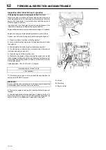
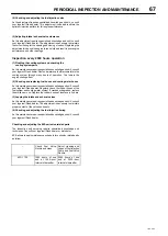
Page 67: ...ion H Press with thumb I Crankshaft V pulley J V belt 2 If necessary adjust the V belt tension deflection To adjust the V belttension loosen the set bolt and move the alternator to tighten the V belt...

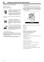
Page 68: ...If operation continues with insufficient battery fluid the battery life is shortened and the battery may overheat and explode Battery fluid tends to evaporate more quickly in the summer and the fluid...

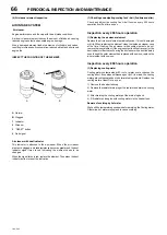
Page 69: ...tem for leaks 3 Replacing the engine oil and engine oil filter 2nd time and after Replace the engine oil every 200 hours operation from 2nd time and on Replace the engine oil filter at the same time 4...

Page 70: ...perationfrom 2nd time and on Inspection every 400 hours operation 1 Replacing the air cleaner element Replace the air cleaner element periodically even if it is not damaged or dirty When replacing the...

Page 71: ...Checking and replacing fuel hoses and cooling water hoses As this maintenance requires specialized knowledge and skill consult your Ingersoll Rand dealer Regularly check the rubber hoses of the fuel s...

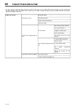
Page 72: ...Starter does not turn Bad cable connections Starter or starter switch failure Safety relay failure Engine stop solenoid malfunction No fuel in the fuel tank No fuel injection Clogged fuel filter eleme...

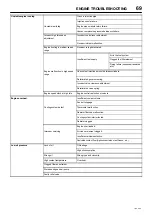
Page 73: ...ection amount between cylinders Deteriorated governor spring Incorrect valve clearance adjustment Deteriorated valve spring Engine speed stuck at high idle Engine control restriction or seizure Engine...

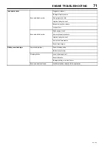
Page 74: ...ance adjustment Cylinder compression leakage Injector nozzle misalignment Low cylinder compression pressure Cylinder bore wear Insufficient air intake volume Air cleaner clogged Restricted air flow Ex...

Page 75: ...ct fuel Water mixing in fuel Excessive white smoke Low compression pressure Injection timing incorrect Low coolant temperature Faulty turbocharger Battery over discharge Low electrolyte level Crack in...

Page 76: ......

Page 77: ......

Page 78: ......

Reviews: