Installation
Operation & Maintenance Manual
23221138 (5/08) Rev B
17
Mounting Unit
Satisfactory installation depends upon the ability of the installer. Refer to the appropriate
foundation plan for the dimensions of the compressor package.
Choose a clean, relatively cool location for the compressor package, and provide ample space
around the unit for general accessibility and to ensure effective heat dissipation. Extreme care
must be taken in locating an air-cooled unit of this type so there is an unrestricted supply of air
to the cooling fan, which pulls air into the package. The air exiting the package must flow away
from the unit so that it may be readily dissipated to atmosphere without recirculating hot air to
the fan intake. Any recirculation of the cooling air may result in an excessively high compressor
operating temperature.
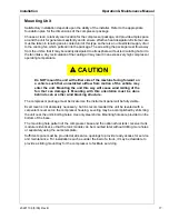
CAUTION
!
Do NOT mount the unit with either side of the machine facing forward on
a vehicle such that unrestricted airflow from motion of the vehicle may
enter the unit. Mounting the unit this way will cause wind milling of the
fan that can damage it. Mounting with this orientation must be done
behind a cab or other wind blocking structure.
The compressor package must be located so the instrument panel will be fully visible.
Exact level is not absolutely necessary, but it is recommended the unit be leveled with a
carpenter’s level set on the compressor housing. Leveling may be accomplished by shimming
the unit near the unit’s bolting holes. Use only steel shims. Mounting holes are provided on the
bottom of the base.
The mounting hole pattern of the compressor base and the optional fuel tank / receiver tank
module is identical, so that the tank module can be mounted later without drilling more holes
or separately using the same template.
Sufficient space must be provided at all service openings to provide ready access for service
and maintenance. For installations such as under the bed of a truck, it may be desirable to
provide a sliding mount tray for the compressor to facilitate servicing.
Summary of Contents for Ingersoll Rand VHP40RMD
Page 2: ...2...
Page 5: ...23221138 5 08 Rev B 5 Safety...
Page 15: ...23221138 5 08 Rev B 15 Installation...
Page 23: ...23221138 5 08 Rev B 23 General Data...
Page 26: ...Operation Maintenance Manual General Data 26 23221138 5 08 Rev B...
Page 27: ...23221138 5 08 Rev B 27 Operating Instructions...
Page 35: ...23221138 5 08 Rev B 35 Maintenance Lubrication...
Page 44: ...44 23221138 5 08 Rev B...

