background image

COMPRESSORS MODEL:

Doosan Infracore Portable Power
1293 Glenway Drive
Statesville, N.C. 28625
DoosanPortablePower.com

P/N: 46680186 (2015) Rev C

P185WDOU-T4F (F89)

P185WDOU-T4F (H28)

XP185WDOUA-T4F (F91)

XP185WDOUA-T4F (H29)

Summary of Contents for P185WDOU-T4F (F89)

Page 1: ...ESSORS MODEL Doosan Infracore Portable Power 1293 Glenway Drive Statesville N C 28625 DoosanPortablePower com P N 46680186 2015 Rev C P185WDOU T4F F89 P185WDOU T4F H28 XP185WDOUA T4F F91 XP185WDOUA T4...

Page 2: ......

Page 3: ...iii...

Page 4: ......

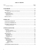
Page 5: ...ce Air Connection s 28 Air Hose Restraint Installation 29 Fuel Safety 29 Safety Decals 30 Safety Decals Summary 31 Safety Decals continued 32 Safety Decals continued 33 Safety Decals continued 34 Safe...

Page 6: ...for XP185WDOUA T4F 55 HP Available for Auxiliary Power Use 56 XP185WDOUA T4F Model 56 OPERATING INSTRUCTIONS 57 Control Panel 58 Instrument Control Panel 58 Instrument Control Panel Indicators 59 Auto...

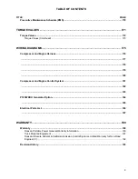
Page 7: ...p 2 Checking Oil Level 98 Step 3 Check Oil Level A B Limits 100 Step 4 Drain Engine Oil 102 Step 5 Replacing Oil Filter 104 Step 6 Final Inspection for Leaks 106 Coolant 108 Checking the Coolant 109 R...

Page 8: ...Exterior Finish Care 139 Field Replacement of Exterior Decals 140 TROUBLESHOOTING 141 Introduction 142 Troubleshooting Chart 143 Diagnostic Codes 149 COMPRESSOR DIAGNOSTIC CODES 151 Compressor Diagno...

Page 9: ...rness 176 177 178 179 180 Compressor and Engine Control System 181 182 183 P185WDOU Generator Option 184 185 Electrical Parts List 186 187 WARRANTY 189 Warranty 190 Doosan Portable Power General Warra...

Page 10: ...10...

Page 11: ...Foreword 11...

Page 12: ...possible be of a type approved by Portable Power Clearly rated for a pressure at least equal to the compressor safety valve setting Compatible with the compressor oil Accompanied with instructions for...

Page 13: ...model s For your own safety and to reduce the risk of injury carefully read understand and observe all instructions described in this manual Portable Power expressly reserves the right to make techni...

Page 14: ...14...

Page 15: ...Safety 15...

Page 16: ...for total security All components which are loose damaged or unserviceable must be rectified without delay Air discharged from this compressor may contain carbon monoxide or other contaminants which w...

Page 17: ...or vent valve before performing any service or maintenance Discharged air contains a very small percentage of compressor lubricating oil and care should be taken to ensure downstream equipment is com...

Page 18: ...it is cooled The flow and service pressure for compressed air is controlled by the operator from the instrument control panel Refer to the product specifications general data section in this manual fo...

Page 19: ...Fuel and its fumes Electric shock and or arc flash Personal injury from improperly relieving pressure before removing filler plugs caps fittings or covers Electrocution or severe electrical shock haza...

Page 20: ...re being allowed to operate it Operator qualifications Only trained personnel are permitted to start operate and shut down the compressor They also must meet the following qualifications Have received...

Page 21: ...hearing protection when operating equipment 12 Follow starting and stopping instructions described in this manual Know how to operate and stop compressor before starting it 13 Make a walk around insp...

Page 22: ...ff O the negative terminal on battery is disconnected Attach a DO NOT START sign to the control panel This will notify everyone that the unit is being serviced and will reduce the chance of someone in...

Page 23: ...icing the equipment 12 Keep the compressor clean and labels legible Replace all missing and hard to read labels Labels provide important operating instructions and warn of dangers and hazards 13 Check...

Page 24: ...ngine owner s manual and the safety guidelines below Operating Safety When running the compressor engine Keep the area around exhaust pipe free of flammable materials Check the fuel lines and the fuel...

Page 25: ...al system to the positive terminal on the weak system Connect the negative terminal of the external system to the negative terminal of the weak system Always disconnect the two systems in reverse orde...

Page 26: ...he reservoir cap until all excess fluid is released and the engine cooling system fully depressurized Follow the instructions provided by the antifreeze supplier when adding or draining the antifreeze...

Page 27: ...contact with the eyes irrigate with water for at least 5 minutes Should compressor oil come into contact with the skin wash off immediately Consult a physician if large amounts of compressor oil are...

Page 28: ...Of Compressed Air Without First Making Sure A Check Valve Is Used Between The Header And The Compressor If This Compressor Is Connected In Parallel With Another Compressor Of Higher Discharge Pressur...

Page 29: ...connection Hoses can fail in areas other than at connecting points and require daily inspection of the hoses for Cuts Cracks Or Kinks Weakened Clamps Due To Rust And Corrosion Damaged Connections Def...

Page 30: ...are identified by the decal heading DANGER WARNING CAUTION NOTICE Decal part numbers are located in the lower right hand corner of each decal and are also listed in the Parts Manual Submit orders for...

Page 31: ...ty hazards Read and follow these instructions If you do not understand these instructions inform your supervisor Red Background Indicates the presence of a hazard which WILL cause serious injury death...

Page 32: ...Safety Safety Decals continued Below is a summary of safety decals which may be included on your compressor 32...

Page 33: ...Safety Safety Decals continued Below is a summary of safety decals which may be included on your compressor 33...

Page 34: ...Safety Safety Decals continued Below is a summary of safety decals which may be included on your compressor 34...

Page 35: ...Safety Safety Symbols Below is summary of the intended meanings for the symbols used on safety compressor 35...

Page 36: ...Safety Safety Symbols continued Below is summary of the intended meanings for the symbols used on safety compressor 36...

Page 37: ...Lifting Transporting and Preparation 37...

Page 38: ...ported in or on the compressor Personal injury or damage to vehicle can result if vehicle is rated below 1000 lb load capacity This chapter provides instructions for preparing the compressor for use I...

Page 39: ...or equivalent and is fully engaged and latched on the lifting bail if equipped See Figure 2 1 Use guide ropes or equivalent to prevent twisting or swinging of the compressor once it has been lifted cl...

Page 40: ...tly to the vehicle bed The air going into the inlet must be relatively free of oil dirt soot and other debris It must be no more than 10 F 5 C over the ambient temperature The inlet and outlet grilles...

Page 41: ...its operating location Never operate compressor without first observing all safety warnings and carefully reading the Operation and Maintenance Manual shipped from the factory with this compressor Se...

Page 42: ...outdoors Clean up spilled fuel immediately Flammable Fuels Do not fill tank when engine is running Do not smoke or use an open flame in the vicinity of the compressor or fuel tank Do not permit smoki...

Page 43: ...ed personnel who have read and understand this section should refill the fuel tank system Lighter fuels can reduce fuel economy or possibly damage fuel system components Do not use diesel fuel blended...

Page 44: ...s 6 Reinstall the fuel tank cap The procedure for fueling refueling the fuel tank is now complete NOTE Cummins recommends the use of ASTM number 2D fuel for optimum engine performance Lubrication Alwa...

Page 45: ...vicing intervals Fill compressor initially with 2 quarts qts of lubricating oil Start compressor and immediately shutdown Add an additional 1 7 quarts to compressor and make sure the oil level is visi...

Page 46: ...46...

Page 47: ...Noise Emission 47...

Page 48: ...ake System or Parts thereof C Enclosure or Parts thereof 2 Removal of any of the following A Fan Shroud B Vibration Mounts C Sound Absorption Material 3 Operation of the Compressor with any of the Enc...

Page 49: ...passed disabled or nonfunctional Daily ACOUSTIC MATERIALS In daily inspections observe these materials Maintain all acoustic material to its original condition or closely as possible Repair or replace...

Page 50: ...operation Unrestricted airflow over the radiator and oil cooler must be maintained at all times during operation 250 HOURS ISOLATION MOUNTS Engine Airend isolation mounts should be inspected after ea...

Page 51: ...04 58 1 Maintenance Log COMPRESSOR MODEL SERIAL NO USER UNIT NO UNIT IDENTIFICATION DEALER DISTRIBUTOR INFORMATION Engine Make Model Purchased From Serial No Purchaser or Owner Address Date Purchased...

Page 52: ...ise Emission Maintenance Record MAINTENANCE RECORD FOR NOISE EMISSION CONTROL AND EXTENDED WARRANTY ITEM NO DESCRIPTION OF WORK HOURMETER READING MAINT INSP DATE LOCATION CITY STATE WORK DONE BY NAME...

Page 53: ...General Data 53...

Page 54: ...12VDC FLUID CAPACITIES Compressor Lubricant gallon litres 3 5 13 2 liters Engine Cooling System gallon litres 3 11 4 liters Engine Crankcase Lubricant gallon litres 2 5 9 5 liters Fuel Tank gallon li...

Page 55: ...2VDC FLUID CAPACITIES Compressor Lubricant gallon litres 3 5 13 2 liters Engine Cooling System gallon litres 3 11 4 liters Engine Crankcase Lubricant gallon litres 2 5 9 5 liters Fuel Tank gallon litr...

Page 56: ...1 An Auxiliary Drive such as a hydraulic pump can be mounted to the auxiliary drive location on the right hand side of the front of the engine 2 The maximum auxiliary drive power from the engine auxi...

Page 57: ...Operating Instructions 57...

Page 58: ...of the Control Operator Panel See Figure 3 1 1 Air Pressure Gauge Indicates Pressure in the Separator Tank 2 Mini Port Display Displays Compressor Operating Parameters and Diagnostic Codes 3 Hour Mete...

Page 59: ...u choices or Increases a value until the end of the Parameter List Menu choices or Maximum Parameter Value is reached DOWN The DOWN Button functions identical to the UP Button with the exception that...

Page 60: ...trol system will automatically power OFF Power can be restored by simply pressing the Power Button In the event of a Fault this feature is not active and the power will remain ON until the Fault has b...

Page 61: ...e 3 2 FIGURE 3 2 ENGINE and COMPRESSOR PARAMETERS Note 1 Only the Parameters that are available from the Engine or Compressor will be Displayed Note 2 Unit times out after 3 minutes of inactivity and...

Page 62: ...Displayed only when the Engine is shutdown The Fault has to be acknowledged by the user by pressing the Enter button The unit does not time out in the Fault display After 60 seconds If the fault is st...

Page 63: ...t has occurred If there are Multiple Alerts pressing the DOWN button will scroll through the various Alerts All Faults and Alerts will be Displayed until the Engine shuts down and then the most severe...

Page 64: ...utton to acknowledge a service has occurred Pressing the ENTER button after the service channels have been displayed acknowledges The message and the display unit returns to the Default Screen If serv...

Page 65: ...N buttons To highlight the desired interval and press the ENTER button to select Use the UP and DOWN buttons to Increase or Decrease the number of hours Hours will decrement with every hour on the eng...

Page 66: ...P buttons to highlight and the ENTER button to select the desired Display setting To Return to the Default Screen of Engine Hours use the DOWN button to highlight the Main Screen Menu Item and press t...

Page 67: ...ss and hold the ENTER button while the Default Screen of Engine Hours is Displayed until the Main Menu appears Scroll to the Setup Option using the DOWN button then press the ENTER button Use the DOWN...

Page 68: ...fluid can cause serious burns Do not open radiator while engine is still hot hot water will spurt out and may cause severe personal injury Combustible gas can cause severe burns blindness or death Kee...

Page 69: ...C or 24VDC Connect the Positive terminal of the external system to the Positive terminal on the weak system Connect the Negative terminal of the external system to the Negative terminal of the weak sy...

Page 70: ...aintain per marks on dipstick Check the fuel level Add fuel as necessary Refer to Engine Operator Manual for fuel specifications Check the compressor lubricating fluid level between bottom and midway...

Page 71: ...ectric heater starting aid To ensure an adequate flow of oil to the Airend never allow the discharge pressure to fall below 50 psi This compressor is equipped with a battery disconnect switch which di...

Page 72: ...imit is reached The first green light on the start button will illuminate 4 If engine fails to start press main power button to remove power from engine Repeat steps 1 3 5 When engine starts the first...

Page 73: ...ne has been started and is running in the unload state at idle speed If there is air demand pressure falls below the load point pressure compressor will load at idle speed by opening the inlet valve A...

Page 74: ...wnstream of the valve may be trapped A vent hole in the service valve will slowly bleed air from the hose Do not disconnect hoses until all pressure has been vented Use the Emergency Stop if equipped...

Page 75: ...efore turning the battery disconnect switch to the OFF position Shutdown Do the following for powering down the compressor by following these procedure 1 Close all Service Valves 2 Allow the engine to...

Page 76: ...w clockwise one full turn 2 Close Service Valves After Starting 1 Push the Service Air button on the Control Panel The unit should speed up and then unload and drop back to IDLE With the unit unloaded...

Page 77: ...Engine Operation 77...

Page 78: ...d to maintain long term optimal engine conditions and best performance In the event that a part must be replaced only genuine Doosan parts as defined by the parts list Parts Manual should be used Doos...

Page 79: ...orized or non factory remanufactured parts may cause critical damage and faults to engine for which Doosan shall not be held liable Consider the following while managing engines 1 Use clean specified...

Page 80: ...ks In the event the compressor controller detects a parameter at a dangerously high or low level the compressor will be automatically shut down with the cause of the shutdown shown on the Mini Port In...

Page 81: ...Do not exchange or disassemble a pipe or hose from the engine fuel circuit engine oil circuit coolant circuit or compressed air circuit while the engine is operating The leaked liquid may cause bodil...

Page 82: ...If you cannot fully understand or have any questions please contact us 2 For safety reasons attach warning signs around engines in operation to keep people other than workers from accessing the engine...

Page 83: ...nstructions provided by the battery manufacturer when checking or handling batteries 8 Only certified professional technicians should repair and maintain engines 9 Only appropriate tools should be use...

Page 84: ...ause critical damage and faults in engine performance 7 Replace parts such as cotter pins gaskets o rings seal rings oil seals and washers with new ones during repairs Reuse of parts may be the cause...

Page 85: ...led before starting work otherwise you may get burned by the heated engine 8 Do NOT work on rotating or operating parts once the engine has been started 9 Discard oil according to the regulations set...

Page 86: ...rious pollution of the drinking water source may occur 4 Classify the oil filters and filter cartridges as environmental pollution waste and discard them according to regulations 5 Classify the antifr...

Page 87: ...rating the compressor Failure to ventilate hot exhaust gases can result in improper functioning compressor and the heat build up can result in melting rubber and or plastic components 1 Before startin...

Page 88: ...ation 1 If oil pressure drops too low it may cause abnormal wear and burning of bearings If oil pressure is too high it may cause oil leakage 2 Continuing to operate the engine after noises or vibrati...

Page 89: ...ing operation shutdown the engine diagnose the cause and fix the fault 4 Check the engine status through the alarm indicator lamp and gauges mounted on the apparatus during operation Engine Oil Pressu...

Page 90: ...d and the lifetime of the engine may be shortened by overloading or high speeds In order to prevent this please follow the guidelines below for the initial 50 hours after delivery of new engine 1 Full...

Page 91: ...and then pick it out again to check The oil pressure may increase with high rpm and decrease with low rpm In addition the pressure of cold oil may be higher at a specific rpm than of warm oil This phe...

Page 92: ...d parts such as the oil pressure sensor oil pump or oil line 3 Check the coolant gauge on the apparatus to ensure the coolant is circulating properly If the coolant level in the supplementary tank is...

Page 93: ...der liner may increase Therefore the engine should be operated within the normal operating temperature If the engine has been sufficiently operated but the temperature of coolant remains below the nor...

Page 94: ...cate between the upper limit and the lower limit of the oil level gauge Engine oil should be periodically replaced based on the regular inspection table and the oil filter and the cartridge should be...

Page 95: ...ed gloves or cloth in pockets Discard exchanged oil according to the regulations set forth by the relevant authorities Disposing of discharged oil into the ground sewers drains rivers or the sea will...

Page 96: ...Operation Procedure for Changing Oil and Oil Filter Step 1 Component Locations Showing oil fill oil filter dipstick and drain locations FIGURE 4 1 SHOWING OIL FILL OIL FILTER DIPSTICK and DRAIN LOCATI...

Page 97: ...erform the following procedure below as follows Before proceeding do the following 1 Move the unit to a flat surface to maintain the engine level 2 Start the engine and then shut down when it reaches...

Page 98: ...Engine Operation Step 2 Checking Oil Level Showing oil fill oil filter dipstick and drain locations FIGURE 4 2 ENGINE OIL LEVEL GAUGE DIPSTICK 98...

Page 99: ...level gauge dipstick handle 3 Pull the handle of the oil level gauge dipstick forward and out See Figure 4 2 4 Clean the indication line of the oil level gauge dipstick with clean cloth 5 Reinsert the...

Page 100: ...Engine Operation Step 3 Check Oil Level A B Limits Showing oil levels between A B limits FIGURE 4 3 CHECK OIL LEVELS A B LIMITS 100...

Page 101: ...ure below as follows Procedure 1 Check if the oil is smeared between the upper limit a and the lower limit b See Figure 4 3 of the oil level gauge dipstick 2 If engine oil is smeared below the lower l...

Page 102: ...Engine Operation Step 4 Drain Engine Oil Showing engine drain location FIGURE 4 4 SHOWING ENGINE OIL DRAIN 102...

Page 103: ...d to drain out of the engine Refer to engine owner s manual 3 Loosen the engine oil drain plug Carefully remove the plug by hand making sure the catch pan is underneath the plug hole Oil will flow rap...

Page 104: ...Engine Operation Step 5 Replacing Oil Filter Showing oil filter location FIGURE 4 5 REPLACING OIL FILTER 104...

Page 105: ...the oil filter Check to make sure the filter gasket has come off with the filter If it s still clinging to the engine mounting plate remove it and any remaining residue Install 1 Cleanly wipe the sur...

Page 106: ...Engine Operation Step 6 Final Inspection for Leaks Performing final inspection for leaks FIGURE 4 6 FINAL INSPECTION FOR LEAKS 106...

Page 107: ...procedure below as follows Procedure 1 Start the engine and then stop it when it reaches a normal temperature 2 Check if engine oil leaks after starting the engine 3 Wait for 5 10 minutes 4 Check the...

Page 108: ...e engine However if the engine is used for a long period the performance of antifreeze and anticorrosion of the coolant degrades Maintain the condition of the coolant through daily inspections and per...

Page 109: ...released remove the reservoir cap When taking out a sample of coolant from the supplementary tank it is difficult to measure the precise concentration Always take out sample by opening the drain plug...

Page 110: ...easure the coolant concentration If the coolant concentration is outside the specified range exchange the coolant Measurement of Coolant Concentration Special Tools FIGURE 5 1 TEST STRIP PRODUCT NUMBE...

Page 111: ...olor table on top of the container and confirm the concentration The concentration indication has to be within the color scope of 33 50 5 The state of additives for anticorrosion is shown on the point...

Page 112: ...ower limit replenish the coolant as follows 1 Remove the supplementary tank cap 2 Replenish coolant until level is between the upper and lower limit of the supplementary tank 3 Install the supplementa...

Page 113: ...uthorities Disposing of exchanged coolant into the ground sewers drains rivers or the sea will cause serious environmental pollution Violation of regulations regarding discard of coolant without obser...

Page 114: ...ngine and wait until engine is cooled 10 Remove the radiator drain plug and drain water 11 Repeat steps 1 8 until the drained water becomes clear 12 Press the hose connected to the radiator to dischar...

Page 115: ...Lubrication 115...

Page 116: ...an specified may be necessary All filters and filter elements for air and compressor oil must be obtained through portable power to ensure the proper size and filtration for the compressor Compressor...

Page 117: ...e hours indicated in the Maintenance Schedule it should be drained of oil If the compressor has been operated under adverse conditions or after long periods in storage an earlier change may be necessa...

Page 118: ...d Warranty CHART 6 1 COMPRESSOR OIL SPECIFICATION Rated Operating Pressure Ambient Temperature Compressor Oil Specification 100 psi to 300 psi 10 F to 125 F 23 C to 52 C Preferred PRO TEC Alternate IS...

Page 119: ...Doosan See Table 6 1 branded Filters can extend Airend Warranty Refer to the Warranty Policy for details or contact your Representative TABLE 6 1 PREFERRED OIL Preferred Oil 1 gal 3 8 Liter 5 gal 19 0...

Page 120: ...120...

Page 121: ...Maintenance 121...

Page 122: ...e various components descriptions and the intervals when maintenance has to take place Fluid capacities can be found in the General Data of this manual For any specification or specific requirement on...

Page 123: ...n this manual that describes the service intervals that should be followed For Normal applications of this compressor This page may be reproduced and used as a checklist by service personnel In more s...

Page 124: ...any maintenance work on a running compressor ensure 1 The work carried out is limited to only those tasks which require the compressor to run 2 The work carried out with safety protection devices disa...

Page 125: ...the event unusual environmental operation conditions exist the schedule should be adjusted accordingly Refer to the Preventive Maintenance Schedule in this manual for recommended servicing intervals C...

Page 126: ...ever comes first replace the separator element and clean the scavenge orifice check valve Refer to the Preventive Maintenance Schedule in this manual for recommended servicing intervals NOTE Excessive...

Page 127: ...essor lubricating and cooling oil has deteriorated and should be changed immediately Refer to LUBRICATION section Installing a new oil filter element when the old gasket remains on the filter head wil...

Page 128: ...alant since this will affect electrical conductance Follow the instructions provided by the antifreeze supplier when adding or draining the antifreeze solution It is advisable to wear personal protect...

Page 129: ...he separator element Examine all hoses and tubes and replace if necessary Reassembly Thoroughly clean the orifice drop tube and filter gasket contact area before reassembly Install the new element Rep...

Page 130: ...ot remove the pressure cap until all excess fluid is released and the engine cooling system fully depressurized Refer to the Preventive Maintenance Schedule in this manual for recommended servicing in...

Page 131: ...ilter element when the old gasket remains on the filter head will cause an oil leak and can cause property damage The air filter elements maintenance should be performed as often as conditions require...

Page 132: ...ment Inspection Check for cracks holes or any other damage to the element by holding it up to a light source or by passing a lamp inside Check the seal at the end of the element and replace if any sig...

Page 133: ...tank s should be filled daily or every eight hours To minimize condensation in the fuel tank s it is advisable to top up after the compressor is shut down or at the end of each working day Drain any s...

Page 134: ...the sleeve and push in past the first resistance to the bottom The mark should be approximately 1 16 inch from the sleeve for the 3 8 inch O D tubing 1 8 inch for the 1 4 inch O D tubing This will ens...

Page 135: ...o the Preventive Maintenance Schedule in this manual for recommended servicing intervals Keep the battery terminals and cable clamps clean and lightly coated with petroleum jelly to prevent corrosion...

Page 136: ...Torque Values in this manual Lubrication Always check the oil levels before a new compressor is put into service If for any reason the compressor oil has been drained it must be re filled with new oil...

Page 137: ...luble Refer to the Portable Compressor Oil Chart Refer to the Preventive Maintenance Schedule in this manual for recommended servicing intervals NOTE If the compressor has been operating under adverse...

Page 138: ...w Refer to Table 7 1 TABLE 7 1 GREASE SPECIFICATIONS Grease Specifications Thickener Type Lithium Complex Dropping Point 215 C 419 F Minimum Consistency NLGI No 2 Additives EP Corrosion Oxidation Inhi...

Page 139: ...paper to repair any scratches or defects necessary 4 Scuff sand the entire area to be painted with a red Scotch Brite pad 5 Wipe the area clean using Dupont 3900S 6 Blow and tack the area to be painte...

Page 140: ...ettle on surface 3 Align decals prior to removing the backing 4 Peel one section of backing from decal while still aligned and squeegee decal from center of the edges to remove air 5 Remove the remain...

Page 141: ...Troubleshooting 141...

Page 142: ...een done 4 If the compressor will still operate is it safe to continue operating it to make further checks Do The Simplest Things First Most troubles are simple and easily corrected For example most c...

Page 143: ...ee Electronic Service Manual Defective sensor Identify and check sensor Replace if necessary See Electronic Service Manual Malfunctioning relay Identify and check relay Replace if necessary See Electr...

Page 144: ...anual Defective sensor Identify and check sensor Replace if necessary See Electronic Service Manual Malfunctioning relay Identify and check relay Replace if necessary See Electronic Service Manual Eng...

Page 145: ...beyond out of level operating limit Reposition or relocate compressor to be more level Wrong engine oil Change engine oil Review engine oil specification Clogged engine oil filter Replace engine oil...

Page 146: ...change compressor oil Clogged fuel filters Service fuel filters See Engine manual Drain clean fuel tanks Add clean fuel Operating pressure too high Reduce pressure to rated operating pressure Recircu...

Page 147: ...ghten or replace Defective or imbalanced fan Replace fan Defective airend drive coupling Replace coupling Engine malfunctioning See troubleshooting in Engine Manual Airend malfunctioning See Complaint...

Page 148: ...functioning inlet unloader Inspect valve Make adjustments per this manual Defective safety valve Replace safety valve Compressor will not unload fast enough Check pressure regulator Check regulation l...

Page 149: ...The Engine Diagnostic Codes Can Also Be Read With The Engine Manufacturer S Service Tool Refer to Engine Fault Codes section in this manual A Service Tool Connector Is Provided In The Electrical Harne...

Page 150: ...150...

Page 151: ...Compressor Diagnostic Codes 151...

Page 152: ...EMPT EXCEEDED AutoStart Attempts Exceeded Compressor not started after 3 crank attempts ALERT CPR CODE 12 FUEL LEVEL LOW Low Fuel Level Fuel level in tank approaching empty ALERT CPR CODE 16 HIGH ENGI...

Page 153: ...R CODE 33 SEP TANK PRES SENSOR Separator Tank Pressure Sensor Separator Tank Pressure Sensor reading out of range FAULT CPR CODE 34 HIGH PRES AT START High Separator Tank Pressure At Start Separator T...

Page 154: ...sor Regulation system pressure sensor reading out of range FAULT CPR CODE 55 E E STOP ACTIVATED Emergency Stop Activated Emergency Stop Button has been activated FAULT CPR CODE 56 LOW START PRESSURE L...

Page 155: ...0 DEF level initiate engine shutdown after 1 minute FAULT CPR CODE 143 ENG INDUCE ACTIVE Inducement Active Engine inducement active see engine diagnostic code ALERT CPR CODE 251 CPR CTRL COMMS Compre...

Page 156: ...156...

Page 157: ...Engine Fault Codes 157...

Page 158: ...Engine Fault Codes Engine Fault Code List 158...

Page 159: ...Engine Fault Codes Engine Fault Code List 159...

Page 160: ...Engine Fault Codes Engine Fault Code List 160...

Page 161: ...Engine Fault Codes Engine Fault Code List 161...

Page 162: ...Engine Fault Codes Engine Fault Code List 162...

Page 163: ...Engine Fault Codes Engine Fault Code List 163...

Page 164: ...Engine Fault Codes Engine Fault Code List 164...

Page 165: ...Engine Fault Codes Engine Fault Code List 165...

Page 166: ...Engine Fault Codes Engine Fault Code List 166...

Page 167: ...Engine Fault Codes Engine Fault Code List 167...

Page 168: ...Engine Fault Codes Engine Fault Code List 168...

Page 169: ...Preventive Maintenance Schedule PMS 169...

Page 170: ...Preventive Maintenance Schedule PMS Preventive Maintenance Schedule PMS Preventive Maintenance Schedule 170...

Page 171: ...Torque Values 171...

Page 172: ...lues Torque Values Fasteners See the following pages for inch torque chart metric torque chart and wheel torque chart All fasteners should be torqued in accordance to size and grade TABLE 1 INCH FASTE...

Page 173: ...Torque Values Torque Values Continued TABLE 2 METRIC FASTENERS Note Cooling Fan Drive Bolts 10 9 M8 x 1 25 should be torqued to 23Nm 17ft lbF Separator Lid Max Bolt torque 166 ft lb 173...

Page 174: ...Torque N m Torque Ft Lbs 13 Wheel 80 90 M12 Bolts 85 95 62 70 15 Wheel 105 115 M14 Bolts 145 155 107 115 16 Wheel 105 115 M16 Bolts 175 185 129 137 16 5 Wheel 105 115 M18 Bolts 205 215 151 159 5 8 Lu...

Page 175: ...Wiring Diagrams 175...

Page 176: ...Compressor and Engine Harness 176...

Page 177: ...177...

Page 178: ...178...

Page 179: ...179...

Page 180: ...180...

Page 181: ...Compressor and Engine Control System 181...

Page 182: ...182...

Page 183: ...183...

Page 184: ...P185WDOU Generator Option 184...

Page 185: ...185...

Page 186: ...Electrical Parts List 186...

Page 187: ...187...

Page 188: ...INTENTIONALLY LEFT BLANK 188...

Page 189: ...Warranty 189...

Page 190: ...Warranty Warranty Doosan Portable Power General Warranty Information 190...

Page 191: ...Warranty Truck Mounted Equipment 191...

Page 192: ...Warranty Doosan Infracore Federal California Emission Control Systems Limited Warranty for Non Road Engines CI 192...

Page 193: ...Revision History Rev Date Description A 11 02 2015 Original Release B 02 16 2017 Added Content in Manual C 03 12 2019 Updated Content in Manual 193...

Page 194: ......

Page 195: ......

Page 196: ...Doosan Infracore Portable Power 1293 Glenway Drive Statesville N C 28625 DoosanPortablePower com Doosan Infracore Portable Power Printed in the U S A...

Reviews: