MAINTENANCE
Operating & Maintenance Manual
Book: 46490694 (03-2010) Rev A
41
Air Cleaner
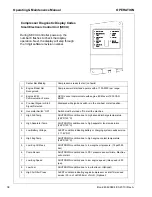
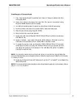
If this unit is equipped with the Optional Full Instrumentation, the SECU Module, located inside
front panel near instrument panel, will Display #9 when either engine or compressor air filter
is restricted.
Weekly squeeze the rubber valve (precleaner dirt dump) on each air cleaner housing to ensure
that they are not clogged.
The air filters restricted sensor will automatically reset after the main power switch is turned to
“OFF.”
To service the air cleaners on all units proceed as follows:
1. Loosen the 3 latches on the sides of the air cleaner cover.
2. Remove air cleaner body.
3. Pull out air cleaner element.
4. Pull out safety element if installed.
5. Install new filters in air cleaner body.
6. Re-install cover on air cleaner body.
7. Close the 3 latches after securing to air cleaner body.
In addition, the air cleaner system (housing and piping) should be inspected every month for
any leakage paths or inlet obstructions. Make sure the air cleaner mounting bolts and clamps
are tight. Check the air cleaner housing for dents or damage which could lead to a leak. Inspect
the air transfer tubing from the air cleaner to the compressor and the engine for leaks.
Make sure that all clamps and flange joints are tight.
Make sure the pre-cleaner dirt dump is pointed within 30° of down.
Gauges
The instruments or gauges are essential for safety, maximum productivity and long service life
of the machine. Inspect the gauges and test any diagnostic lamps prior to start-up. During
operation observe the gauges and any lamps for proper functioning. Refer to Operating
Controls, for the normal readings.
Fuel Tank
CLEAN fuel in the fuel tanks is vitally important and every precaution should be taken to
ensure that only clean fuel is poured or pumped into the tank.
When filling the fuel tank on this unit, by methods other than a pump and hose, use a CLEAN
non-metallic funnel.
Battery
Keep the battery posts-to-cable connections clean, tight and lightly coated with a grease. Also
the electrolyte level in each cell should cover the top of the plates. If necessary, top-up with
clean distilled water.
Summary of Contents for P185WJD-D75
Page 2: ...2...
Page 5: ...Book 46490694 03 2010 Rev A 3 Foreword...
Page 8: ...Operating Maintenance Manual Foreword 6 Book 46490694 03 2010 Rev A...
Page 9: ...Book 46490694 03 2010 Rev A 7 DRAWBAR NOTICE...
Page 11: ...DRAWBAR NOTICE Operating Maintenance Manual Book 46490694 03 2010 Rev A 9...
Page 12: ...Operating Maintenance Manual DRAWBAR NOTICE 10 Book 46490694 03 2010 Rev A...
Page 13: ...Book 46490694 03 2010 Rev A 11 Safety...
Page 16: ...Operating Maintenance Manual Safety 14 Book 46490694 03 2010 Rev A...
Page 17: ...Safety Operating Maintenance Manual Book 46490694 03 2010 Rev A 15...
Page 18: ...Operating Maintenance Manual Safety 16 Book 46490694 03 2010 Rev A...
Page 20: ...Operating Maintenance Manual Safety 18 Book 46490694 03 2010 Rev A...
Page 22: ...Operating Maintenance Manual Safety 20 Book 46490694 03 2010 Rev A...
Page 23: ...Book 46490694 03 2010 Rev A 21 Noise Emission...
Page 28: ...Operating Maintenance Manual Noise Emission 26 Book 46490694 03 2010 Rev A...
Page 29: ...Book 46490694 03 2010 Rev A 27 GENERAL DATA...
Page 32: ...Operating Maintenance Manual GENERAL DATA 30 Book 46490694 03 2010 Rev A...
Page 33: ...Book 46490694 03 2010 Rev A 31 OPERATION...
Page 41: ...Book 46490694 03 2010 Rev A 39 MAINTENANCE...
Page 51: ...Book 46490694 03 2010 Rev A 49 LUBRICATION...
Page 53: ...Book 46490694 03 2010 Rev A 51 Troubleshooting...
Page 62: ...Operating Maintenance Manual Troubleshooting 60 Book 46490694 03 2010 Rev A...
Page 63: ...Revision History Rev Level EC Number Comments A B C D E SVC31192 Original Release...

