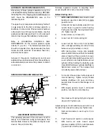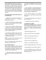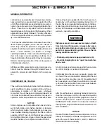
AUTOMATIC SHUTDOWN/DIAGNOSTICS
Should any of these problem situations occur, the
unit will automatically shutdown and stop. BEFORE
restarting the unit or flipping the POWER switch to
“Off”, check the DIAGNOSTICS area on the
instrument panel.
The upper four (4) lamps are electronically “latched”
to only respond to the first or primary signal for a
shutdown. In other words, if the automatic shutdown
is the result of one of these four problems, only that
particular problem lamp will be lit. And the lamp will
remain lit as long as the batteries provide power.
Refer
to
OPERATING
CONTROLS
AND
INSTRUMENTS for the various problem signal
criteria (
°
F, psi, etc.). The indicated problem area
should be inspected for a physical cause (low fluid,
broken fan belt, evidence of excessive heat, etc.)
and corrections made.
Sensors (1) through (3), Switches (4) and (5) and
additional low oil pressure switch (mentioned above)
will automatically reset when the problem condition
is corrected.
SPEED AND PRESSURE REGULATION
L
N
M
PR
H
AC
J
P
GC C
K
E
F
B D
BV
A
G
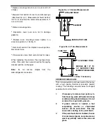
ADJUSTMENT INSTRUCTIONS
The operating pressure of this unit was set at the
factory to the maximum rating (at full speed). See
General Data. However, this pressure may be reset
down to 150 psi (1050 kPa).
Normally, regulation requires no adjusting; but if
proper adjustment is lost, proceed as follows:
Before Starting Unit --
1.
WITH UNIT STOPPED
, disconnect rod end
bearing on governor cable (GC) at engine
governor lever.
2.
At bracket (A) near butterfly valve (BV) run
nut (B) back on governor cable housing.
Push governor cable housing toward lever
(C). Tighten nut (D).
3.
Loosen screw (J) on lever (C).
4.
Loosen nut (E) to relax spring (G)
5.
Loosen nut (H). Turn rod (L) in Air Cylinder
(AC) until approximately 3/4 inch (20 mm)
between nut (H) and flats on rod (L).
6.
With locking pliers, clamp onto butterfly
valve shaft and rotate and hold it so butterfly
valve is fully shut. Place a wrench on lever
screw (K) and rotate butterfly valve lever (C)
so air cylinder rod (L) fully bottoms out in air
cylinder. While holding the butterfly valve
closed AND holding air cylinder shaft fully in,
tighten lever screw (J). Then release hold
on butterfly valve shaft and lever.
7.
Turn rod (L) One and one--half rounds out of
rod end bearing. Tighten nut (H). Rotate
butterfly shaft/lever (C), open and close,
several times to assure that linkage is not
binding.
8.
With engine governor lever in full speed
position, reconnect rod end bearing.
9.
Take slack out of spring (G) by moving nuts
(E) and (F). Tighten nuts.
Adjust spring so it is full stretched, and nut (F) is at
far end of rod, closest to spring (G). Tighten nuts.
10.
Start unit and allow to warm up for 3 to 5
minutes.
11.
Push “Service Air” button on control panel.
12.
With service air valve closed, adjust
pressure regulator (PR) to rated pressure
(*) plus 30 psi (70 kPa) as follows:


