3
Section 3. Setup and Calibration Guide
Power connections:
The PC-400 is powered from a wall mounted transformer or the internal
rechargeable battery. The transformer has a power cord which plugs into the
power jack located on the back of the scale.
RS-232 Connections:
The PC-400 has a standard RS-232 output. To use this feature, the optional RS-
232 cable (P/N PCOPT05) is required. To access the RS-232 port at the rear of
the scale, simply remove the rubber plug that seals the headphone jack style
receptacle. Plug one end of the RS-232 connector into the headphone style jack
located on the rear of the scale. Attach the other end to your computer or printer.
Calibration and Parameter Setup:
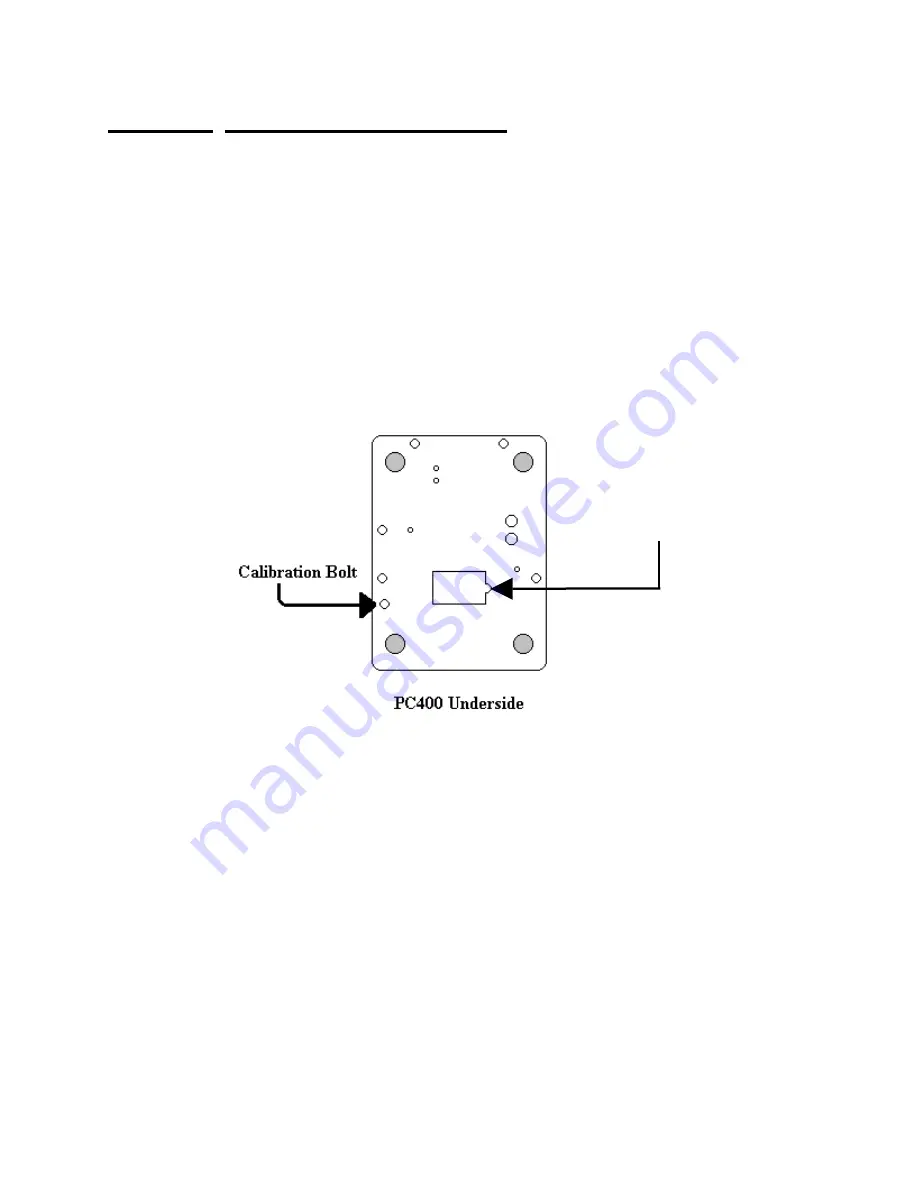
1) After applying power to the PC-400, remove the platter, turn the scale over. If
the calibration bolt has a lead and wire seal, you will require the assistance of
a state certified scale technician to retain legal for trade status. Remove the
calibration bolt as shown above, place a thin blunt object through the hole and
press straight down. The scale should enter the Setup/Calibration mode, and
the scale should display “
div 2.5
” (or “
div 5.0
“or “
div 10
” depending on the
scale resolution.)
2) Turn the scale upright, replace the platter and press the UNITS button twice.
The scale should now display “
CAL 0
”.
3) Remove all weight from the scale platter. Press ZERO. Wait for the scale to
count down from “
7
” to “
0
”. If the scale detects motion, the display will restart
the count. When finished, the display will return “
CAL F5
”.
Battery
Compartment
Cover


